18 PowerFlex 750-Series Products with TotalFORCE Control
Rockwell Automation Publication 750-PC100A-EN-P - December 2016
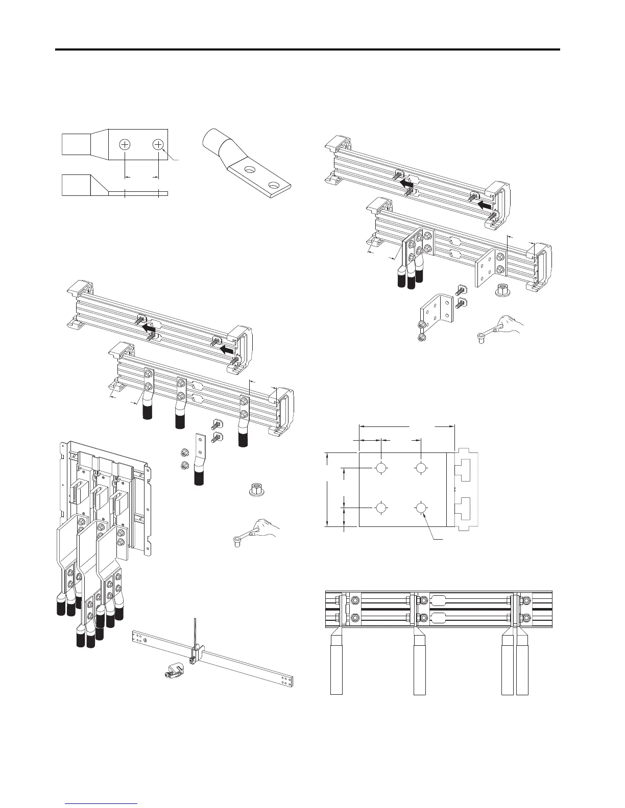
Customer Power Connections
AC line input power and output motor connections are made by using customer-supplied barrel lugs that are
either crimp or mechanical type. Barrel lugs that are used to make the power cable connections to bus bars must
have the dimensions in the following graphic.
UL-Listed Barrel Lug Dimensions
Use the vendor-recommended tooling to fasten crimp type terminals to cabling. Torque mechanical type
terminals according to vendor instructions.
Bus Bar Connections
AC line input power and output motor cables with appropriate barrel lugs are connected directly to bus bars and
use the fastening hardware provided. Keep the wire connections at least 51 mm (2 in.) away from the ends of
the extruded bus bar. Clamp kits, SK-RM-GRNDCLMP-nn, are available for making connections to the PE ground
bar.
L-Bracket Connections
Power cable connections in entry and exit wire bay are made using L-brackets. The M10 hardware that is
required to fasten the L-brackets to the extruded bus bar is provided. Wires with appropriate barrel lugs can be
bolted to both sides of the L-brackets if necessary. Up to four conductors can be attached to each L-bracket.
Attach the conductors to the L-brackets using M12 or 0.5 in. diameter bolts, nuts, and washers. Bellville spring
washers, or equivalent, are recommended. Keep the L-bracket connections at least 51 mm (2 in.) away from the
ends of the extruded bus bar.
Additional Power Terminal L-Brackets
PowerFlex 755T entry and exit wire bays come equipped with L-brackets. If an application requires additional
L-brackets, kit number 20-750-MLBRKT-F8M is available. Each kit contains three L-brackets and mounting
hardware.
L-Bracket Approximate Dimensions
When using mechanical barrel lugs, which may be large, be sure to maintain adequate spacing to adjacent
wires, terminals, and other parts.
Typical Barrel Lug Connection to L-Bracket Options
44.5 mm
(1.75 in.)
Ø 12.7 mm
(0.5 in.)
38.0 N•m (336 lb•in)
M10: 15 mm
M12: 19 mm
51 mm
(2 in.)
51 mm
(2 in.)
Frame 8 Cable Connections
Customer-supplied M12 hardware.
Ground Clamp
38.0 N•m (336 lb•in)
M10: 15 mm
M12: 19 mm
51 mm
(2 in.)
51 mm
(2 in.)
Cable Connections
Customer-supplied M12 hardware.
46.0 mm
(1.81 in.)
25.5 mm
(1.04 in.)
85.1 mm
(3.35 in.)
44.5 mm
(1.75 in.)
110.0 mm
(4.33 in.)
17.8 mm
(0.70 in.)
Ø11.0 mm
(0.43 in.)
Left Side Right Side Both Sides - Up to three lugs.

 Loading...


