PowerFlex 750-Series Products with TotalFORCE Control 3
Rockwell Automation Publication 750-PC100A-EN-P - December 2016
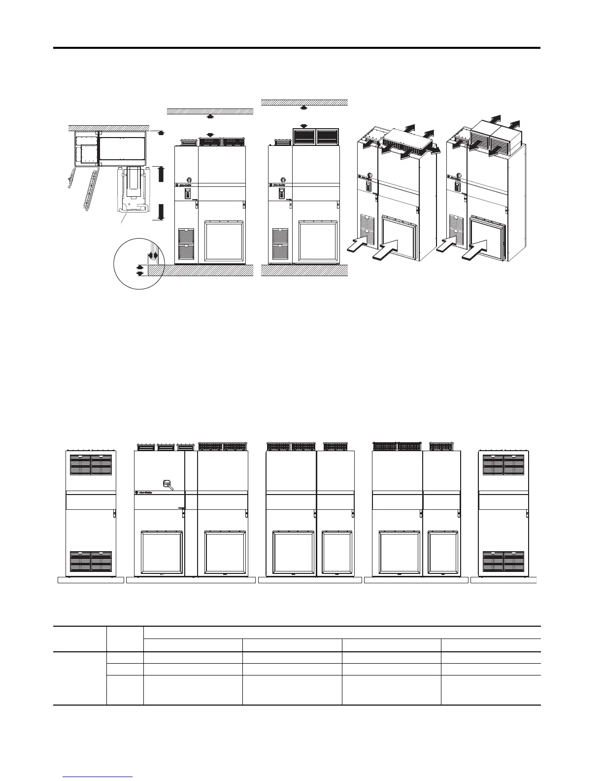
Minimum Mounting Clearances for Operation and Servicing
Specified vertical clearance requirements are intended to be from the PowerFlex 750-Series product with TotalFORCE control to the closest object that can restrict airflow through the cabinet. The product must be mounted in a vertical
orientation as shown and must make full contact with the mounting surface. In addition, inlet air temperature must not exceed the ambient temperature specification.
Mounting Considerations
• Install the product upright on a flat and level surface.
• Verify that the cabinet is square, vertical, and stable.
• Verify that the filter and debris screens are installed.
• Do not expose to dust or metallic particles.
• Do not expose to a corrosive atmosphere.
• Protect from moisture and direct sunlight.
Recommended Mounting Hardware
Fastener size: M12 (property class 8.8, minimum)
Approximate Weights
Some products are divided for shipment. The weight of each section and the total weight are listed in the tables in this section.
Shipment Sections
This diagram illustrates how products are divided for shipment.
Approximate Maximum Drive and Bus Supply Weights
Device Frame Size Approximate Maximum Weight, kg (lb)
Input and Power Bay with Entry Wire Bay with Exit Wire Bay with Entry and Exit Wire Bay
755TL drives 8 Total: 900 (1984) – Total: 987 (2176) –
9 Total: 1683 (3710) – Total: 1770 (3902) –
10 Left section:
Right section:
Tota l:
1553 (3423)
1370 (3021)
2923 (6444)
Left section:
Right section:
Tota l:
1630 (3593)
1370 (3021)
3000 (6614)
Left section:
Right section:
Tot al :
1553 (3423)
1457 (3213)
3010 (6636)
Left section:
Right section:
Tot al :
1640 (3616)
1457 (3213)
3097 (6829)
762 mm
(36 in.)
0
254 mm
(10 in.)
203 mm
(8 in.)
Airflow through the cabinet must not be impeded.
Top View
20-750-MCART1
IP21, UL Type 1 IP54, UL Type 12
Platform measurements are installation limits per NEC requirements.
IP21, UL Type 1
200 mm (7.9 in.)
IP54, UL Type 12
250 mm (9.8 in.)
Wire Bay
(Optional)
Left Section Center Section Right Section Wire Bay
(Optional)

 Loading...


