26 PowerFlex 750-Series Products with TotalFORCE Control
Rockwell Automation Publication 750-PC100A-EN-P - December 2016
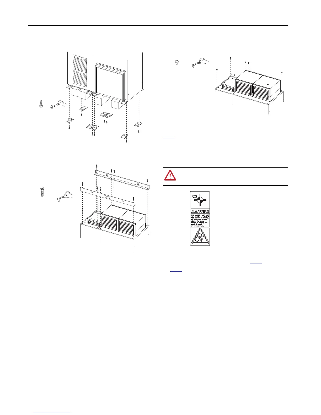
Remove Shipping Cleats
Place the cabinet on supports, such as wooden beams, that provide enough space to remove the bolts that
secure the cleats to the cabinet.
Remove Cabinet Lifting Angle
After the cabinet is in its final position, remove the lifting angles.
Secure Roof Panels
After the lifting angles are removed, use the hardware supplied to secure and seal the roof panels. If a cabinet
section will be joined with another cabinet section, don’t install hardware in the positions where the top bracket
sets are installed. See Align and Join Cabinet Sections on page 28.
Join Cabinets
Products that are divided for shipment are joined at the installation site. For detailed cabinet assembly
procedures see the PowerFlex 750-Series Products with TotalFORCE Control Installation Instructions, publication
750-IN100
for the following procedures.
• Align and level cabinets to be joined
• Power module and LCL filter removal
• Joinery hardware installation
• Bus bar splicing
Module Handling
PowerFlex 750-Series Service Cart (20-750-MCART1) and PowerFlex 755TM Power and Filter Module Storage
Hardware (20-750-MINV-ATIP) are recommended to handle, and temporarily store, modules during
installation. See the following publications for more information.
• PowerFlex 750-Series Service Cart Installation Instructions, publication 750-IN105
• PowerFlex 755TM Power and Filter Module Storage Hardware Installation Instructions, publication
750-IN106
M12
19 mm
M12
38 N•m (336 lb•in)
19 mm
ATTENTION: LCL filter modules and power modules have a high center of gravity and a tip-over
hazard exists. To guard against death, serious personal injury, or equipment damage, do not
subject the module to high rates of acceleration or deceleration while transporting. Do not push
or pull above the points indicated on the module.
M12
20 N•m (177 lb•in)
19 mm
M12 screws with integral
paint-piercing rubber washers.
This label, affixed to the module chassis,
identifies the center of gravity.

 Loading...


