2 PowerFlex 750-Series Products with TotalFORCE Control
Rockwell Automation Publication 750-PC100A-EN-P - December 2016
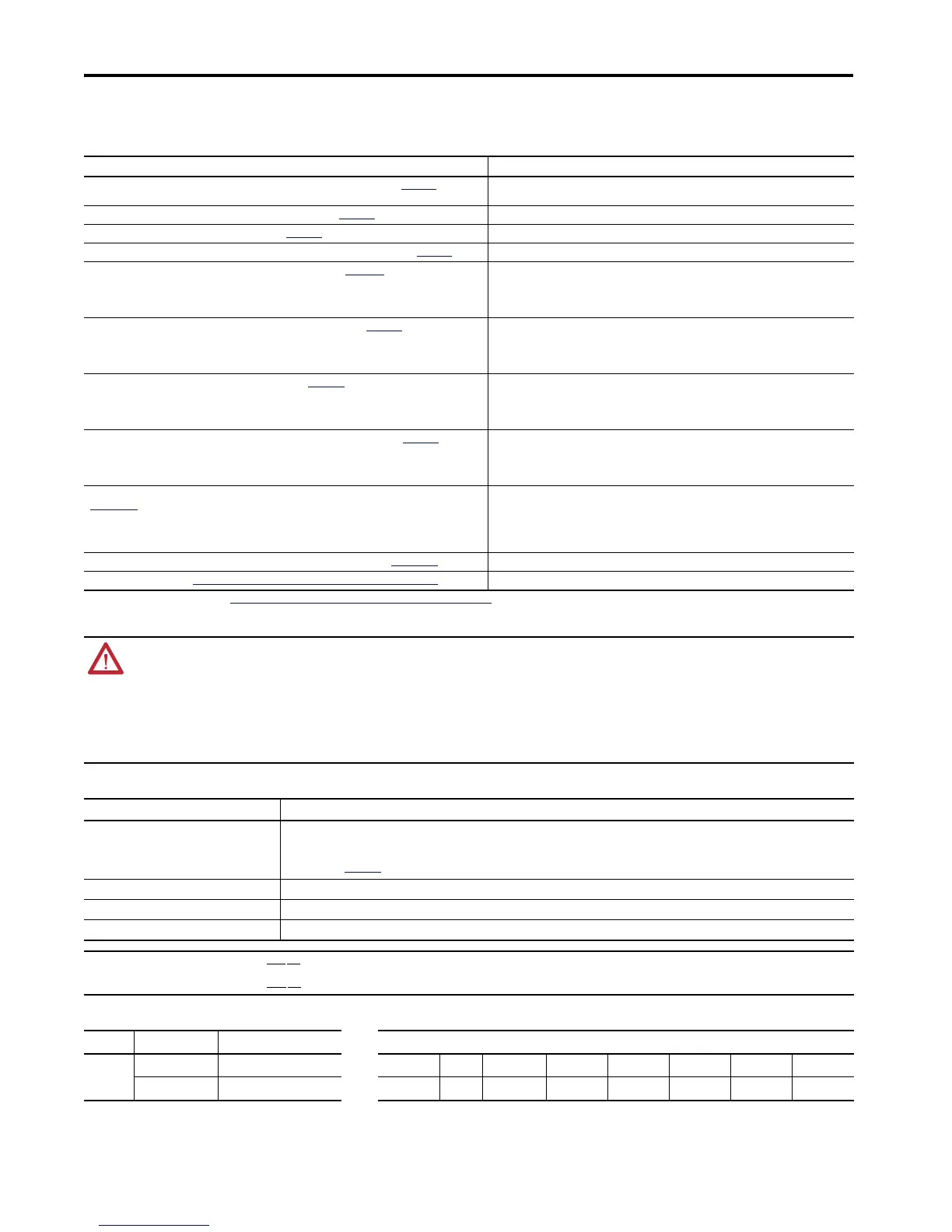
Additional Resources
These documents contain additional information concerning related products from Rockwell Automation.
Environmental Specifications
Enclosure Options
Resource Description
PowerFlex® 750-Series Products with TotalFORCE Control Installation Instructions, publication 750-IN100
Provides the basic steps to install PowerFlex 755TL drives, PowerFlex 755TR drives, and PowerFlex 755TM
bus supplies.
PowerFlex 755TM IP00 Open Type Kits Installation Instructions, publication 750-IN101
Provides instructions to install IP00 Open Type kits in user-supplied enclosures.
PowerFlex 750-Series Service Cart Instructions, publication 750-IN105
Provides detailed set-up and operating instructions for the module service cart and lift extension option.
PowerFlex 755TM Power and Filter Module Storage Hardware Installation Instructions, publication 750-IN106
Provides detailed installation and usage instructions for this hardware accessory.
PowerFlex Drives with TotalFORCE Control Programming Manual, publication 750-PM100
Provides detailed information on:
• I/O, control, and feedback options
• Parameters and programming
• Faults, alarms, and troubleshooting
PowerFlex 750-Series Products with TotalFORCE Control Technical Data, publication 750-TD100
Provides detailed information on:
• Drive and bus supply specifications
• Option specifications
• Fuse and circuit breaker ratings
PowerFlex 755TM IP00 Open Type Kits Technical Data, publication 750-TD101
Provides detailed information on:
• Kit selection
• Kit ratings and specifications
• Option specifications
PowerFlex 750-Series Products with TotalFORCE Control Hardware Service Manual, publication 750-TG100
Provides detailed information on:
• Preventive maintenance
• Component testing
• Hardware replacement procedures
Drives in Common Bus Configurations with PowerFlex 755TM Bus Supplies Application Techniques, publication
DRIVES-AT005
Provides basic information to properly wire and ground the following products in common bus
applications:
• PowerFlex 755TM Common Bus Inverters
• PowerFlex 750-Series AC and DC Input Drives
• Kinetix 5700 Servo Drives
Wiring and Grounding Guidelines for Pulse Width Modulated (PWM) AC Drives, publication DRIVES-IN001
Provides basic information to properly wire and ground PWM AC drives.
Product Certifications website, http://www.rockwellautomation.com/global/certification/overview.page
Provides declarations of conformity, certificates, and other certification details.
You can view or download publications at http://www.rockwellautomation.com/global/literature-library/overview.page
. To order paper copies of technical documentation, contact your local Allen-Bradley distributor or Rockwell
Automation sales representative.
ATTENTION: Only qualified personnel familiar with adjustable frequency AC drives and associated machinery should plan or implement the installation, start up, and subsequent maintenance of the system. Failure to
comply can result in personal injury and/or equipment damage.
ATTENTION: Incorrectly applied or installed PowerFlex 750-Series products with TotalFORCE control can result in component damage or a reduction in product life. Wiring or application errors such as under sizing the
motor, incorrect or inadequate AC supply, or excessive ambient air temperatures may result in malfunction of the system.
ATTENTION: To avoid an electric shock hazard, verify that there is no AC input and DC bus voltage before servicing. Remove power and wait five minutes before you open the cabinet door. Use the test points provided to
take these measurements (See pages 19…22 for test point locations):
• Verify that there is no AC input voltage present using the R/L1, S/L2, and T/L3 test point sockets in the input bay by measuring L to L and L to GND.
• Verify that there is no AC input voltage present using the R, S, and T testpoint sockets in the input bay by measuring L to L and L to GND.
• Verify that there is no DC bus voltage present using the +DC to -DC testpoints in the input bay by measuring +DC to -DC, +DC to GND, and -DC to GND.
Category Specification
Ambient temperature IP21, UL Type 1: -20…+40 °C (-4…+104 °F) Frames 8…12, All Ratings
IP54, UL Type 12: -20…+40 °C (-4…+104 °F) Frames 8…12, All Ratings
Ambient temperature of 50 °C (122 °F) or 55 °C (134 °F) with derating. See Derating Guidelines in the PowerFlex 750-Series Products with TotalFORCE Control Technical
Data, publication 750-TD100
.
Storage temperature -40…+70 °C (-40…+158 °F)
Relative humidity 5…95% non-condensing
Pollution degree PowerFlex 750-Series products with TotalFORCE control are designed to meet Pollution Degree 2 per UL61800-5-1.
IMPORTANT PowerFlex 750-Series products must
not be installed in an area where the ambient atmosphere contains volatile or corrosive gas, vapors, or dust. If the product is to be stored, it must be stored in an area where
it is not exposed to a corrosive atmosphere.
PowerFlex 750-Series products must
not be stored or installed in an environment that contains conductive pollutants.
Frames Enclosure Type Enclosure Code (Position 6) Catalog Number Explanation (20G1G3D302ANANNNN)
8…12 IP21, UL Type 1 3
Position
1…34 5678…1011…18
IP54, UL Type 12 4
Description
Type Cooling Type Input Type Enclosure Voltage Rating Rating Options

 Loading...


