22 PowerFlex 750-Series Products with TotalFORCE Control
Rockwell Automation Publication 750-PC100A-EN-P - December 2016
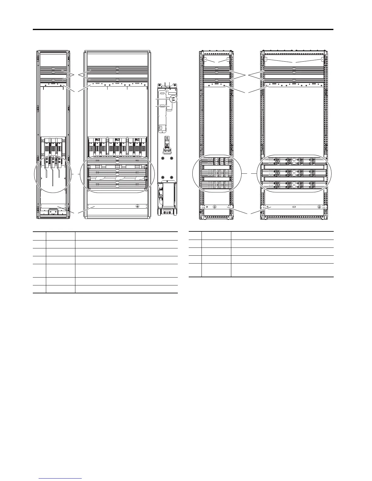
Frames 8…12 Common Bus Inverters Optional Entry and Exit Wire Bays
Item Name Description
1 DC bus DC power supply
2 Control bus Control power supply
3 Power bus U/T1, V/T2, W/T3 motor connections
4 PE grounding bar Terminating point to chassis ground for incoming AC line and motor shield.
PE ground bar clamps, kit number SK-RM-GRNDCLMP-nn, are available.
5 Testpoints DC+, DC- and R/L1, S/L2, T/L3 voltage testpoint sockets
6 Nameplate Power module and LCL filter module nameplate locations
Frame 10 (Layout is typical for Frames 9 through 12.)Frame 8
Item Name Description
1 DC bus DC power supply
2 Control bus Control power supply
3 Power bus U/T1, V/T2, W/T3 motor connections
4 PE grounding bar Terminating point to chassis ground for incoming AC line and motor shield.
PE ground bar clamps, kit number SK-RM-GRNDCLMP-nn, are available.
400 mm (15.7 in.) 800 mm (31.5 in.)

 Loading...


