SLC 500 BASIC and BASIC-T Modules 21
Publication 1746-IN009B-EN-P - August 2005
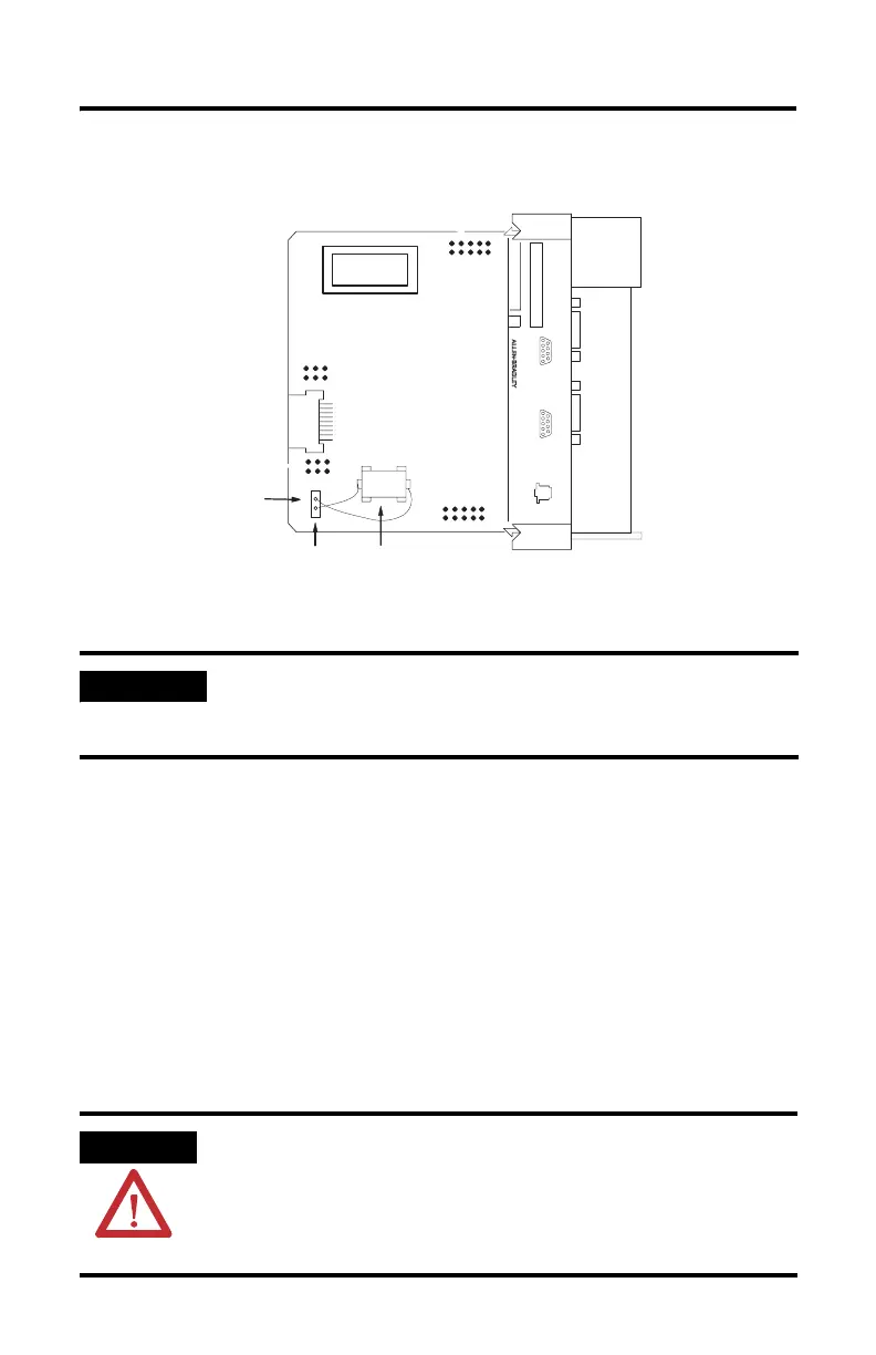
Figure 15 Battery Location
3. Unplug the battery connector.
4. Remove the battery from the retaining clips.
5. Insert a new battery into the battery retaining clips.
6. Plug the battery connector into the socket with the red lead wire on top and
the white lead wire on the bottom.
7. Insert the module into the SLC 500 chassis.
8. Restore power to the SLC 500 power supply.
Battery Handling
IMPORTANT
The module has a capacitor that provides 30 minutes of battery
back-up while the battery is disconnected. Data in RAM is not lost
if the battery is replaced within 30 minutes.
ATTENTION
Do not charge the batteries. An explosion could result or cells
could overheat causing burns.
Do not open, puncture, crush, or otherwise mutilate the batteries.
An explosion may result, exposing toxic, corrosive, or flammable
liquids.
SLC 500
BASIC MODULE
CAT SER
SERIAL NO.
FRN
12345
6789
CONFIG
12345
6789
DF1
DH485
Red WIre
White WIre
Lithium Battery

 Loading...


