18 SLC 500 BASIC and BASIC-T Modules
Publication 1746-IN009B-EN-P - August 2005
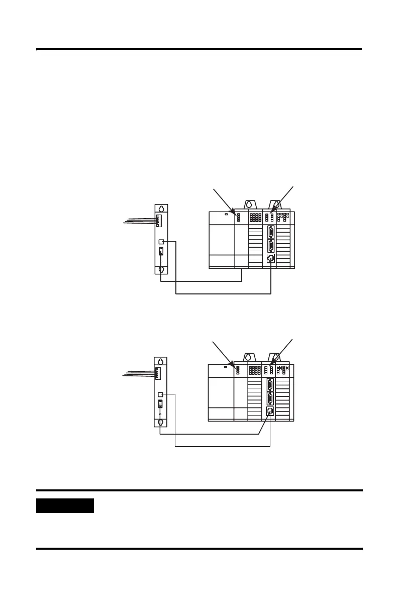
Wire to the DH485 Port
Port DH485 can communicate to user devices through the DH485 communication
mode. Use a 1747-C10 cable or 1747-C13 cable to connect the module to a link
coupler interfaced with the DH485 network.
Figure 13 Connecting the Module to a DH485 Network
IMPORTANT
The 1747-C13 cable acts only as a communication link and does
not carry 24V dc power. Use a 1747-C10 cable or 1747-C11 cable
to carry power from the controller to the link coupler, or from the
module to the link coupler.
To DH485 Network
To DH485 Network
SLC 5/01, 5/02, and
5/03 Controller
SLC 5/04 or 5/05
Controller
BASIC or BASIC-T Module
BASIC or BASIC-T Module
1747-AIC
Link Coupler
1747-AIC
Link Coupler
1747-C13 Cable
1747-C13 Cable
1747-C10 or -C11 Cable
1747-C10 or -C11 Cable

 Loading...


