SLC 500 BASIC and BASIC-T Modules 17
Publication 1746-IN009B-EN-P - August 2005
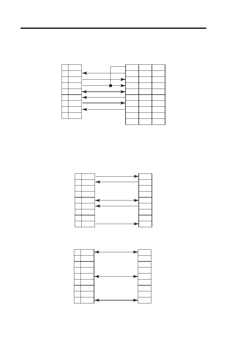
Figure 10 RS-232/423 Wiring Diagram - 1746-BAS Module or 1746-BAS-T Module
to Printer (Hardware Handshaking Enabled, Standard Printer Adapter Cable)
(1)
Figure 11 RS-422 Wiring Diagram
Figure 12 RS-485 Wiring Diagram
N.C.1
RXD2
TXD3
DTR4
COM5
DSR6
RTS7
CTS8
N.C.9
CD
TXD
RXD
DSR
COM
DTR
CTS
RTS
RI
8
2
3
6
7
20
5
4
22
1
3
2
6
5
4
8
7
9
GND 1
(2)
BASIC DTE DCE 9-Pin 25-Pin
(1) The 1747-CP3 cable works in this application.
(2) Connect to the shield of the cable.
TXD1
RXD2
3
4
COM5
RXD+6
7
8
TXD+9
RXD
TXD
COM
TXD+
RXD+
BASIC
TRXD-1
2
3
4
COM5
6
7
8
TRXD+9
TRXD-
COM
TRXD+
BASIC

 Loading...


