14 SLC 500 BASIC and BASIC-T Modules
Publication 1746-IN009B-EN-P - August 2005
Hardware Handshaking
The module uses the following rules when hardware handshaking is enabled. The
module:
• does not transmit until CTS (Clear to Send) becomes active, and
• examines DSR (Data Set Ready) following the receipt of a character.
If DSR is active, the character is placed in the input queue. If DSR is inactive, the
character is assumed to be noise and is discarded.
DTE and DCE Overview
DTE - Data Terminal Equipment
The serial ports are configured as 9-pin Data Terminal Equipment (DTE), as are
most terminals or computer ports.
IMPORTANT
You need to know whether the device connecting to the module
has a DTE or DCE interface. Figures 8 through 12, starting on
page 16, are provided to help you make the appropriate
connection.
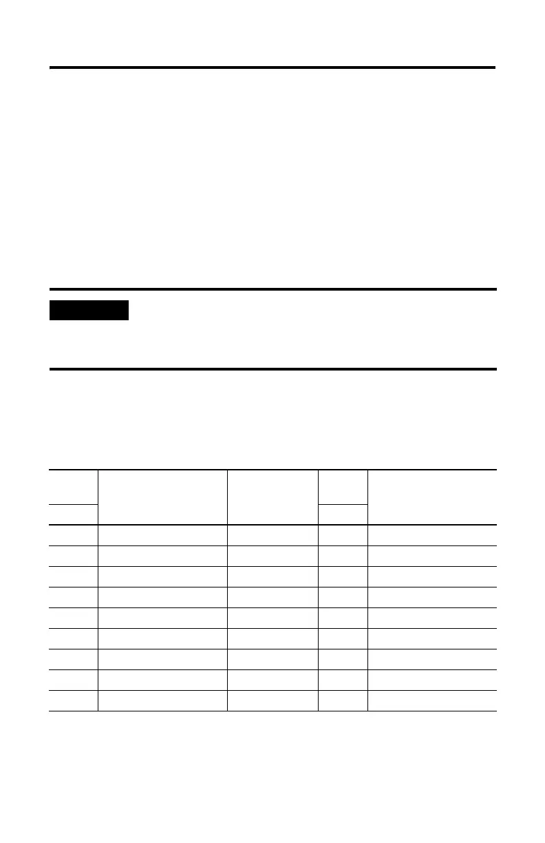
DTE 9
Pinout
Signal
Description
Signal from DTE
Perspective
DTE 25
Pinout
Signal
Description
Pin # Pin #
1 NC-No Connection Input 8 CD-Carrier Detect
2 RXD-Received Data Input 3
3 TXD-Transmitted Data Output 2
4 DTR-Data Terminal Ready Output 20
5 COM-Signal Common Shared 7
6 DSR-Data Set Ready Input 6
7 RTS-Request to Send Output 4
8 CTS-Clear to Send Input 5
9 NC-No Connection Input 22 RI-Ring Indicator

 Loading...


