SLC 500 BASIC and BASIC-T Modules 15
Publication 1746-IN009B-EN-P - August 2005
DCE - Data Communication Equipment
Devices such as modems are Data Communication Equipment (DCE). The pinouts
on these terminals are defined for ease of interfacing with DTE equipment.
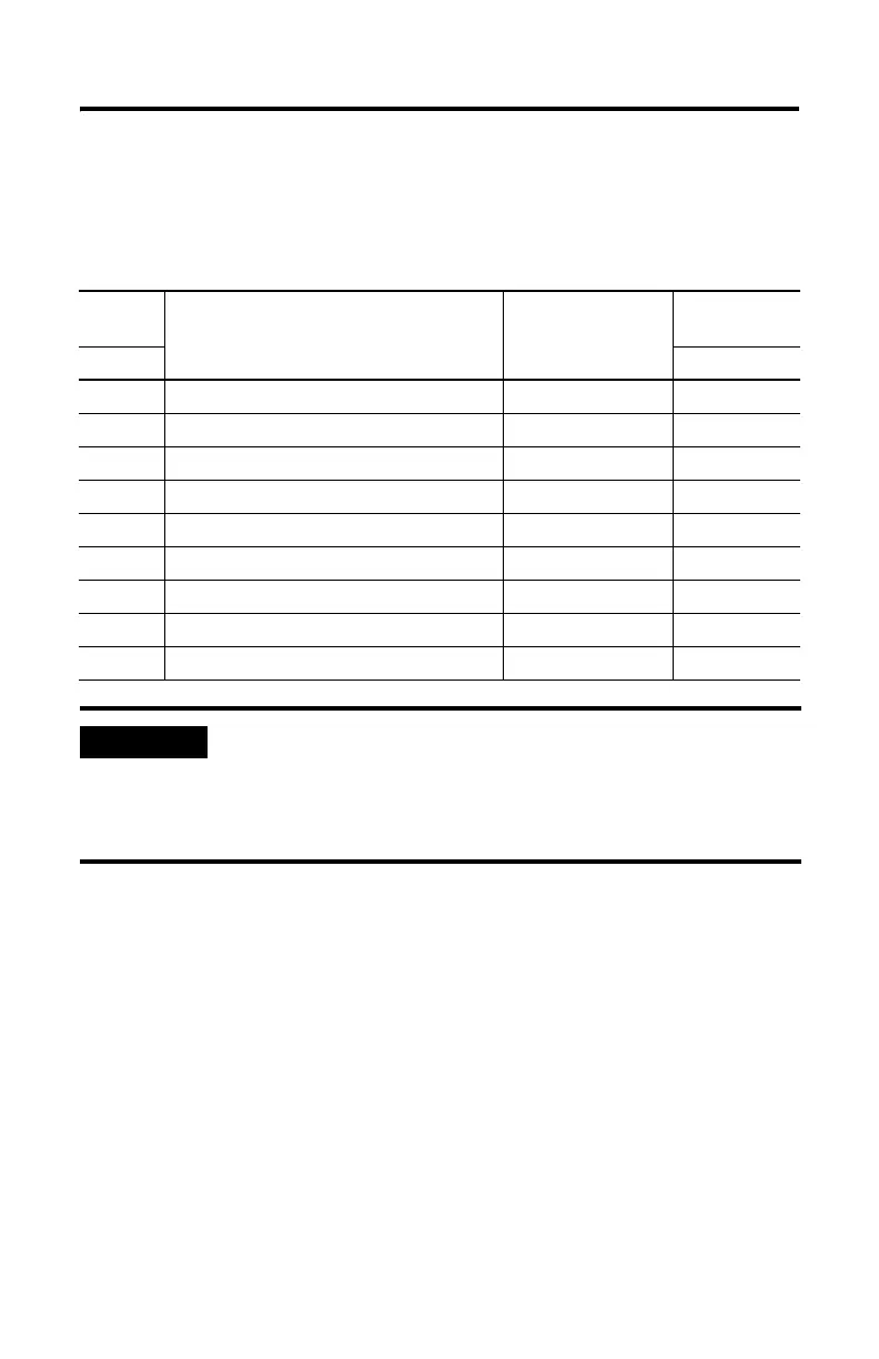
DCE 9
pinout
Signal Description Signal from DCE
Perspective
DCE 25
pinout
Pin # Pin #
1 CD-Carrier Detect Output 8
2 RXD-Received Data Output 3
3 TXD-Transmitted Data Input 2
4 DTR-Data Terminal Ready Input 20
5 COM-Signal Common Shared 7
6 DSR-Data Set Ready Output 6
7 RTS-Request to Send Input 4
8 CTS-Clear to Send Output 5
9 RI-Ring Indicator Output 22
IMPORTANT
All signal directions listed in the previous two tables are valid. For
example, TXD, Transmitted Data, is a DTE output but is also a
DCE input. The signal description is the same for DTE and DCE
but the direction of the signal (perspective) has changed based on
whether you have a DTE or DCE device.

 Loading...


