16 SLC 500 BASIC and BASIC-T Modules
Publication 1746-IN009B-EN-P - August 2005
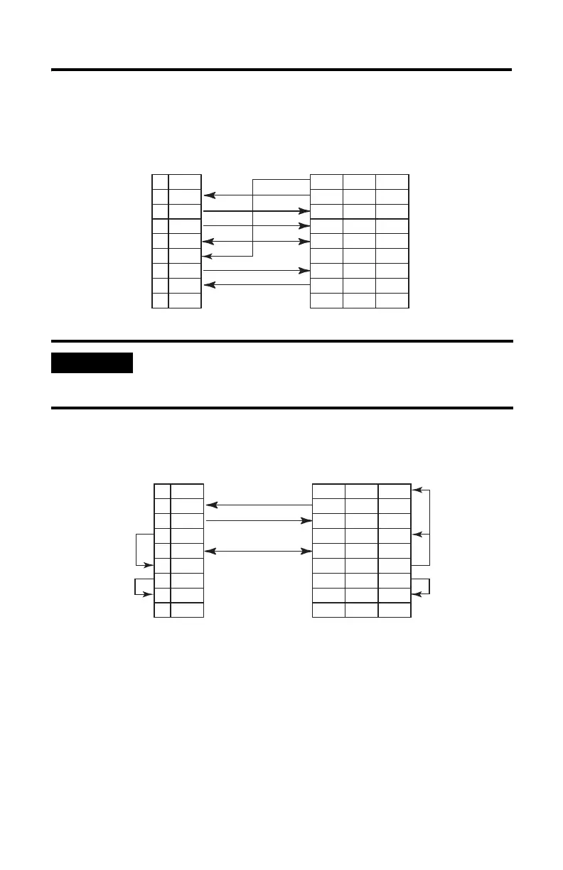
Figure 8 RS-232/423 Wiring Diagram - 1746-BAS Module or 1746-BAS-T Module
to a Modem (Hardware Handshaking Enabled)
Figure 9 RS-232/423 Wiring Diagram - 1746-BAS Module or 1746-BAS-T Module
to DTE Device (Hardware Handshaking Disabled)
IMPORTANT
For DCE devices other than modems, connect the DSR of the
module with the DSR of the device. The CD signal of the device
(other than a modem) is not used.
N.C.1
RXD2
TXD3
DTR4
COM5
DSR6
RTS7
CTS8
N.C.9
CD
RXD
TXD
DTR
COM
DSR
RTS
CTS
RI
8
3
2
20
7
6
4
5
22
1
2
3
4
5
6
7
8
9
BASIC DTE DCE 9-Pin 25-Pin
N.C.1
RXD2
TXD3
DTR4
COM5
DSR6
RTS7
CTS8
N.C.9
DCD
TXD
RSD
DSR
COM
DTR
CTS
RTS
GND
8
2
3
6
7
20
5
4
1
1
3
2
6
5
4
8
7
(1)
(3)
(2)
(2)
(2)
(2)
BASIC DTE DCE 9-Pin 25-Pin
(1) Connect to the shield of the cable.
(2) Jumpers are only needed if you cannot disable the hardware handshaking on the port.
(3) This is a N.C. for the 1747-KE module, 1746-BAS module, or 1746-BAS-T module.

 Loading...


