MN-35949 • Rev 04 • 06/16 • Combitherm® CT PROformance™ Series • Technical Service Manual • 35
• Grease Collection Hose Assembly is attached to the
oven in the back.
• The hose guide bracket can be attached on either the
le side or the right side toward the back. Placement
on the le side is recommended whenever possible.
Thumb screws are in position for this purpose.
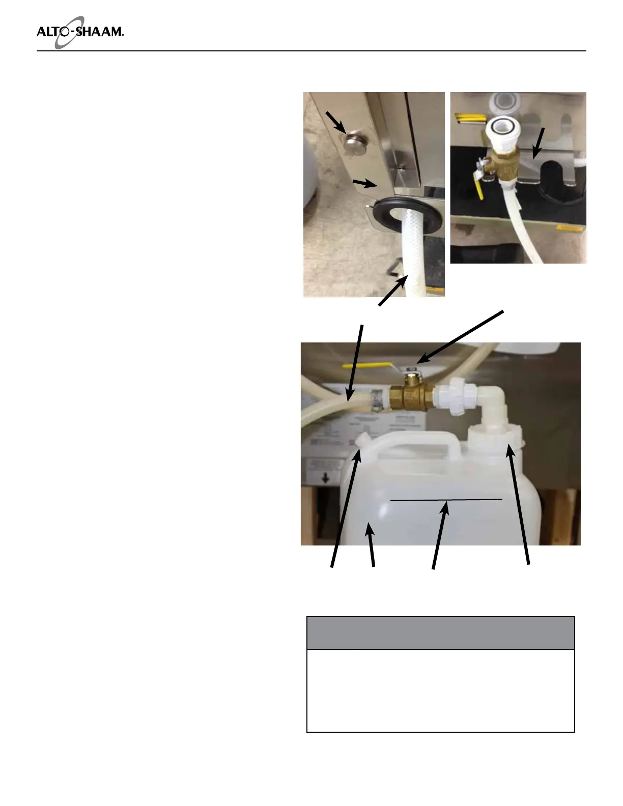
Remove thumb screws, position hose guide bracket
and secure screws (photo a). Thread grease hose
through the guide.
• The hose hanger bracket can be attached on either
the le side or the right side toward the front of the
oven. Placement on the le side is recommended
whenever possible. Philips screws are in position
beneath the oven for this purpose. Remove Philips
screws, position hose hanger bracket and secure
screws (photo b). The hanger bracket is used to
secure the grease collection hose while changing
grease collection containers.
• Place Grease Collection Containers inside the tray
of the Mobile Grease Collection Cart. Roll into place
next to the oven and apply the caster brake.
• Loosen vent cap on container. Pull out the Grease
Collection Hose Assembly from the back of the unit.
Remove collection container ll cap (photo c).
• Screw Grease Collection Hose Assembly on to
collection container until snug.
• Turn ball valve handle to the ON position.
• If this auxiliary function has been chosen while
setting your cooking mode, the automatic grease
collection system is electronically activated during
the cooking process [u.s. patent 8,997,730 b2]. It is
designed to save labor and provide greater employee
safety by eliminating the need to handle hot grease
in shallow pans.
• Grease Collection container has a 5 gallon (19 liter)
capacity and holds approximately 3 full loads of
poultry grease.
• At a minimum, empty and clean the container when
material reaches the ll line on the bottle or at 4
gallons to avoid hot grease over ow.
• Turn the ball valve handle to the OFF position.
• The ball valve handle must be in the OFF position
when changing the collection container.
• Unscrew the container ll cap.
• Using a new container, screw Grease Collection
Hose Assembly on to collection container until snug.
• Turn ball valve handle to the ONposition.
On/Off
Ball Valve
Grease Collection Hose
Container
Fill Cap
Grease
Collection
Container
Vent
Cap
Recommended
Capacity
To prevent SERIOUS INJURY or PROPERTY DAMAGE:
ALWAYS apply caster brakes on mobile carts,
appliances, or accessories when stationary. Equipment
on casters can move or roll on uneven oors.
Check grease collection connections and replace the
containers when lled to the recommended capacity.
WARNING
A
B
C
Thumb screw
Hose guide
bracket
bracket
Organizing Programmed Recipes
Options
Connecting the Optional Grease Collection System
 Loading...