EasyManua.ls Logo

AMX PRO-DP8 DECOR PROLINK FLUSH MOUNT KEYPAD PANEL User Manual

AMX PRO-DP8 DECOR PROLINK FLUSH MOUNT KEYPAD PANEL
27 pages
To Next Page IconTo Next Page
To Previous Page IconTo Previous Page
Page #15 background image
Wiring and Installation
10
PRO-DP8 Decor 8-Button Wall Panel
2. Connect the PROlink connector to the panel (see the Preparing captive wires section on
page 8).
3. Check PROlink LED on the rear side of the panel. If the green LED flashes once every 2
seconds, the panel is communicating properly with the Pack. If the LED is on and not flashing,
disconnect the PROlink connector and recheck all PROlink connections; reconnect the
PROlink connector to the panel and verify the LED is flashing once every 2 seconds.
PROlink status LED
The green LED on the rear panel of the PRO-DP8 is the PROlink status LED. This LED indicates
the communication status of the panel on the PROlink bus:
! Flashing (once every 2 seconds) indicates that PROlink communications are working
properly.
! Full-on indicates that the panel is not communicating with the PROlink bus. Check the
PROlink wiring to the Pack and to any other panels. Refer to the Troubleshooting section
on page 12 for details.
Testing
The following steps describe how to test the PRO-DP8 to verify it is working properly:
1. Disconnect power from the PRO-DP8.
2. Reconnect the power supply to the panel. Check for a blinking green LED on back of the
PRO-DP8 panel to verify proper operation.
3. Press Presets 1-10 (default) to cycle through Preset lighting levels.
4. Press Off to turn lights off.
If this test fails, refer to the Troubleshooting section on page 12.
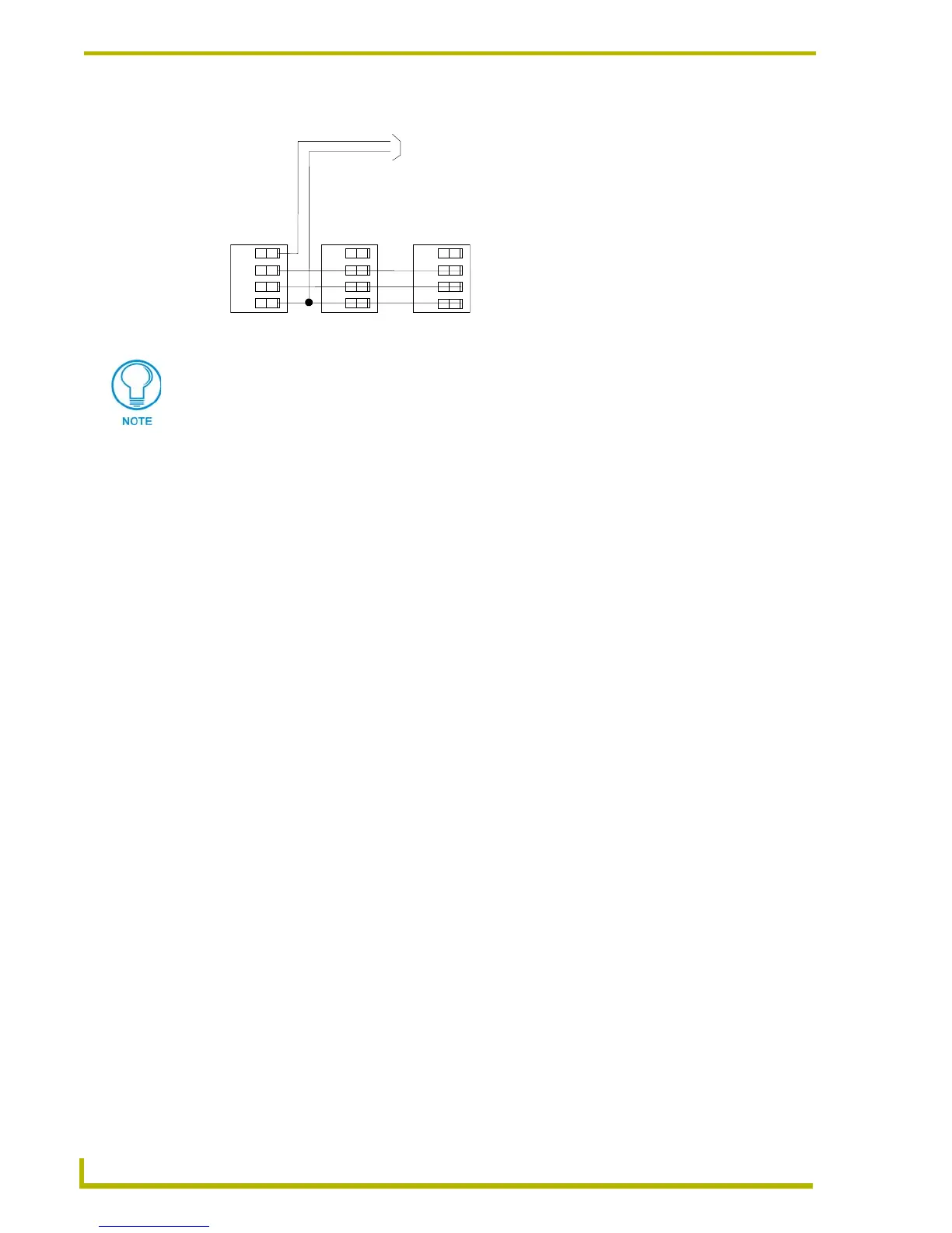
FIG. 2 PROlink wiring diagram using an external 12 VDC power supply
PWR (+)
GND (-)
12 VDC power supply
PRO-DP8
Pack 1
Pack 2
+12
PR+
PR-
GND
+12
PR+
PR-
GND
Do not connect the PWR wire to the PROlink connector’s PWR (+) terminal on the
control system side of the connector.

Questions and Answers:

AMX PRO-DP8 DECOR PROLINK FLUSH MOUNT KEYPAD PANEL Specifications

General IconGeneral
BrandAMX
ModelPRO-DP8 DECOR PROLINK FLUSH MOUNT KEYPAD PANEL
CategoryController
LanguageEnglish

Summary

Presets, Channels and Zones

Packs

Wiring and Installation

Preparing the PRO-DP8 and Dimmer Control Cards

Instructions for preparing the PRO-DP8 panel and its associated dimmer control cards for installation.

Wiring the PRO-DP8

Provides instructions and guidelines for wiring the PRO-DP8 panel using PROlink connectors and cables.

Using a PROlink 4-pin connector for data and power

Step-by-step guide on connecting the PRO-DP8's PROlink connector to dimmer Packs for data and power.

Testing

Provides steps to test the PRO-DP8 panel after installation to ensure proper operation and communication.

Troubleshooting

Offers solutions to common installation problems encountered with the PRO-DP8 panel.

DIP Switch Configuration

DIP Switch Functions (1-8)

Details the operational assignments and functions of the 8 DIP switches located on the back of the PRO-DP8 panel.

Using Switches 1, 2 and 3 to Set Button Offset Values

Explains how to use DIP switches 1-3 to set offset values for panel pushbuttons, affecting preset numbering.

Using Switches 4 and 5 to Specify Which Pack(s) to Control

Describes how DIP switches 4 and 5 determine which dimmer Packs (1-3) the PRO-DP8 panel communicates with.

Using Switch 7 to Enable Either Preset Recall mode, or Zone Select/Preset Ramping

Explains how DIP switch 7 controls panel behavior between Preset Recall and Zone Select/Ramping modes.

Panel Programming/Operation

Related product manuals