- 18 -
C139603300_2.fm
IT
AUS
SDE
FR
ES
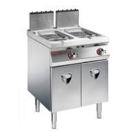
Natural gas
1 - Turn off the gas supply tap.
2 - Open the hatch (A).
3 - Undo the pressure connection screw (B).
4 - Connect the pressure gauge (C) to the pressure
test point.
5 - Unscrew the cap (D) and if necessary fit the spring
(F) and adjuster screw (E) (supplied on request).
6 - Turn the gas supply tap back on.
7 - Light the burner (see page 7) and turn the screw
(E) until the pressure gauge shows a pressure of
0,8 kPa.
8 - Check the stability of the flame.
N.B.: after adjusting, seal the screw with paint.
9 - Turn off the burner, disconnect the pressure
gauge and restore the initial conditions after com-
pleting the operation.
Liquid gas
1 - Turn off the gas supply tap.
2 - Open the hatch (A).
3 - Unscrew the cap (D).
4 - Remove the adjuster screw (E) and the
spring (F) and replace them with the cap (G)
(supplied on request).
5 - Screw the cap (G) fully down.
6 - Restore the initial conditions after completing the
operation.
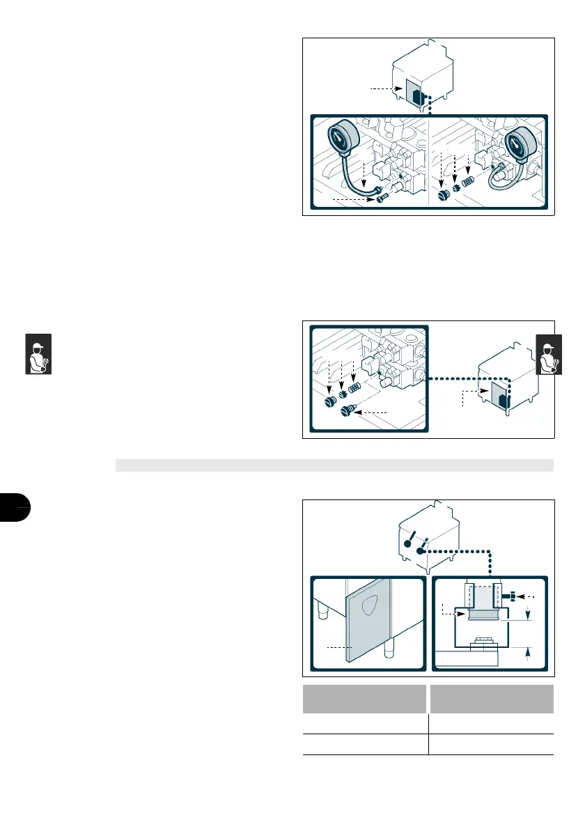
ADJUSTING BURNER PRIMARY AIR
To carry out this operation, proceed as follows.
1 - Turn off the gas supply tap.
2 - Open the hatch (A).
3 - Undo the locking screw (B).
4-Set the bush (C) at the distance (D) shown in the
table.
5 - Tighten the screw (B).
6 - Close the door (A).
Gas family
Distance
(D)
(mm)
NGN 26±1
ULPG 26±1
C
A
B
D E F
IDM-39603311600.tif
IDM-39603312100.tif
FED
AG
D
A
BC
IDM-39603314700.tif

 Loading...