Installation Procedure
24 Autopulse-442R 50098:F 05/24/2001
6HWWLQJ0RGHRI2SHUDWLRQ
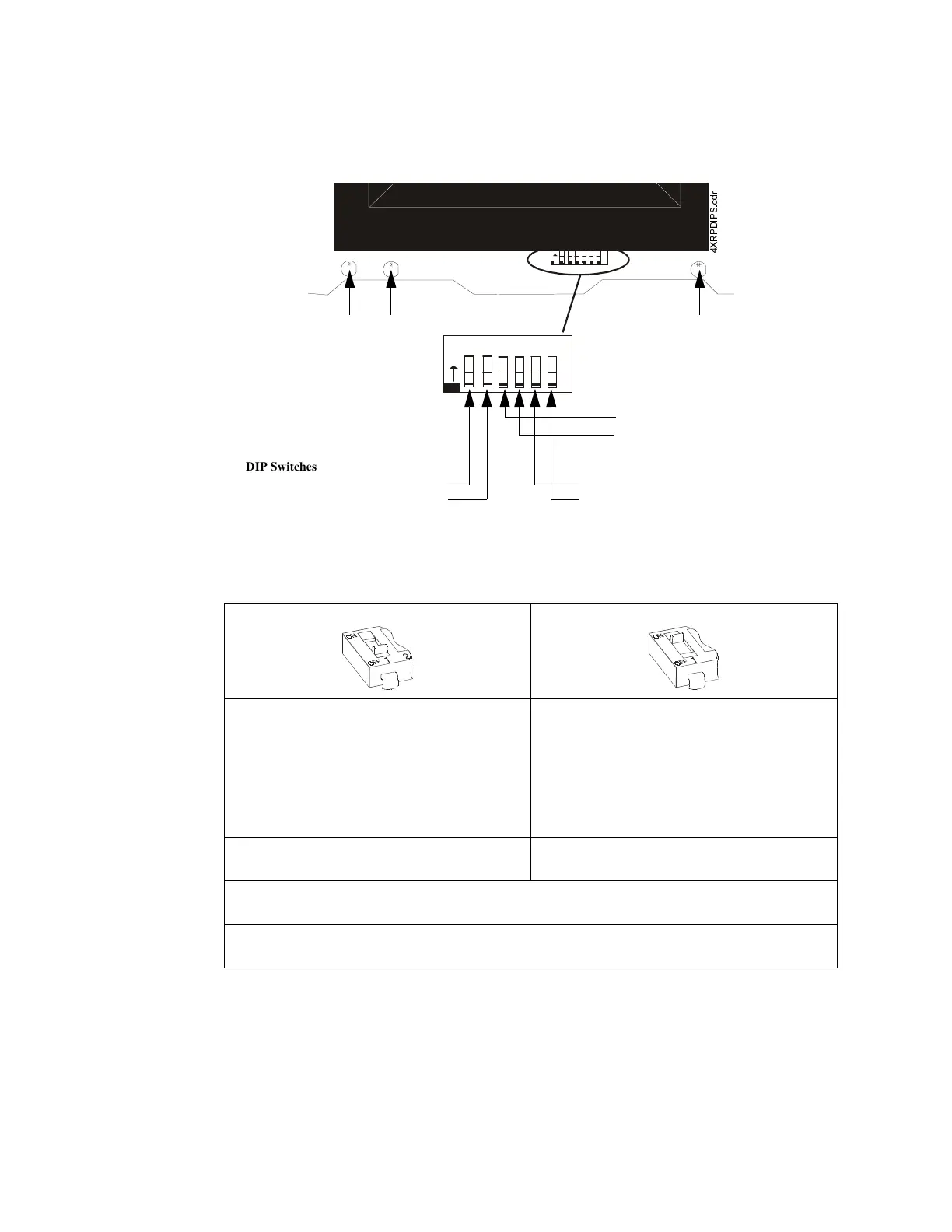
Select operating mode by setting the DIP switches on SW1; basic programming options are shown
in this section. After any changes are made to the configuration switches, the panel must be reset.
For Canadian use, refer to “Sprinkler Supervisory Tracking” in Section 3.9.
&URVV=RQH
Select the desired mode of operation and set SW1 DIP switch 1 per the appropriate column.
1
2
3456
O
N
1
2
34
5
6
O
N
Battery Fail LED Ground Fault LED Micro Fail LED
DIP Switches for Setting Abort Option
Switch 5: Abort Option
Switch 6: Abort Option
;53',36FGU
DIP Switches for Basic Programming
Switch 1: Cross Zone
Switch 2: Supervisory
DIP Switches for Setting
Releasing-Circuit Delay Timer
Switch 3: Delay Timer
Switch 4: Delay Timer
Switch #1 OFF Switch #1 ON
Output 1
is activated by an alarm on either
Zone 1
or
Zone 2
.
Output 1
(Pre-discharge alarm) is activated by the
first alarmed zone in the system. Initiation of an
alarm on the other zone will shut this output off.
Output 2
is activated by an alarm on either
Zone 1
or
Zone 2
. Output 2 will pulse at 60 ppm while timer
is running or frozen by abort. Output 2 will sound
steadily upon release (time out).
Output 2
is activated when alarms occur on both
Zone 1
and
Zone 2
. Output 2 will pulse at 60 ppm
while timer is running or frozen by abort. Output 2
will sound steadily upon release (time out).
The
Releasing-Circuit Delay Timer
will start when-
ever an alarm occurs on either
Zone 1
or
Zone 2
.
The
Releasing-Circuit Delay Timer
will start when
alarms occur on both
Zone 1
and
Zone 2
.
Outputs 3 and 4
will be activated when the timer expires (provided that Output 4 is functioning as a
releasing circuit - set via DIP Switch 2).
Note: Outputs 1 and 2 refer to Notification Appliance Circuits. Output 3 refers to a releasing circuit. Output
4 is determined by setting switch 2. Zones 1 and 2 refer to Initiating Device Circuits.
 Loading...