Installation Procedure
26 Autopulse-442R 50098:F 05/24/2001
=RQH5HOD\0RGXOH
3RZHU8S3URFHGXUH
WARNING: Prior to energizing this panel, notify all personnel and authorities,
including any personnel who may be working on, around, or near this unit.
CAUTION: Observe polarity of batteries. Improper connection will cause damage
and VOID WARRANTY. Do not connect battery leads until instructed to do so per
the power-up procedure. System will be operational and could damage the PC
board or injure personnel.
1.
Wire Primary Power Connections.
Primary power
required for the Autopulse-442R and Autopulse-442RC
panels is 120 VAC, 50/60 Hz, 1.2 amps and primary power
for the Autopulse-442RE is 220/240 VAC, 50/60 Hz, 0.6
amps. Overcurrent protection for this circuit must comply
with Article 760 of the National Electrical Code (NEC) and/
or local codes. Use #14 AWG or larger wire with 600 volt
rating.
The power supply will operate normally and the panel will be fully operational from 102-132
VAC. However, to keep the batteries fully charged, input power must be maintained at nom-
inal 120 VAC. A separately fused and protected power connection to the panel should be
supplied to prevent voltage fluctuation and interruption of power.
2.
Apply Primary Power.
Notify personnel who may be working with the AC power circuits
before removing the “Out of Service” tag and restoring power to the circuit. The green AC
power LED will illuminate. The Trouble LED will illuminate until battery power is applied.
3. Connect Secondary Power as shown in Figure 2.13.
When the system is powered, the
trouble LED will clear. If the trouble light does not extinguish, refer to Troubleshooting
Table in Appendix C.3.
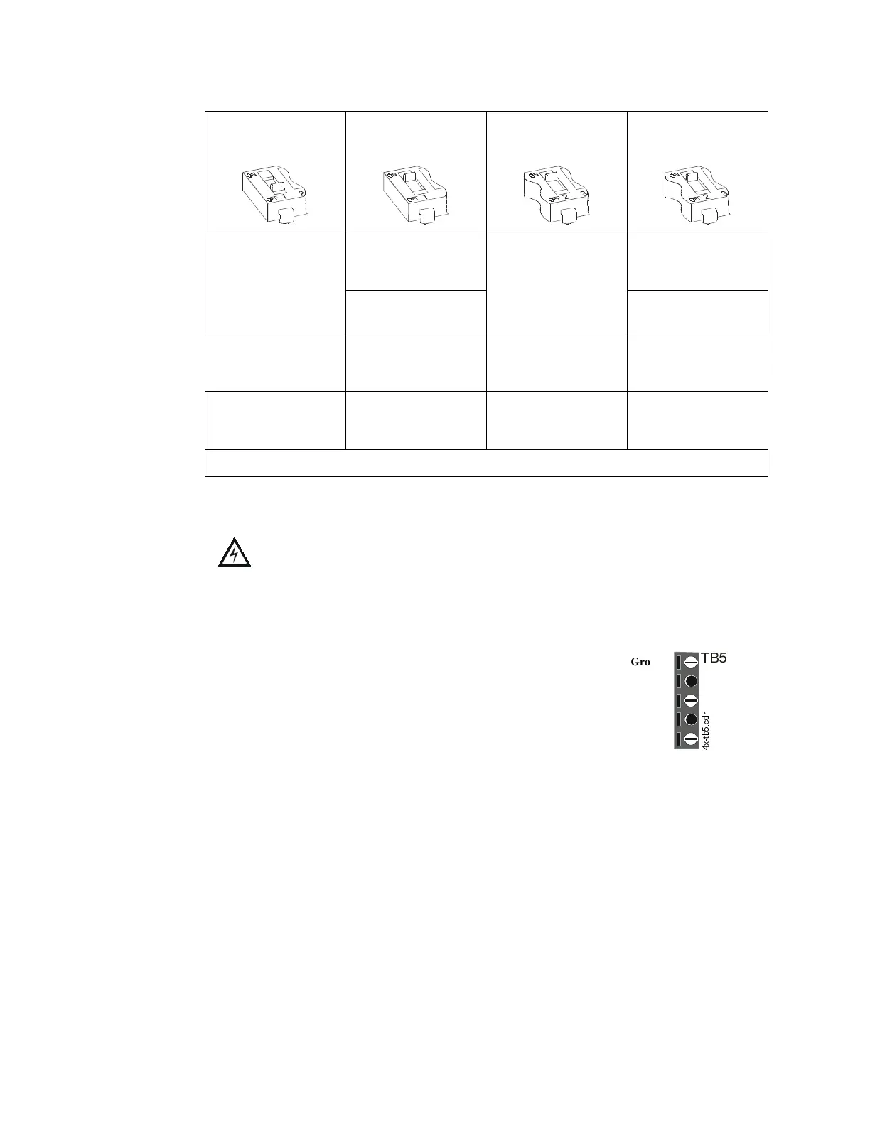
DIP #1 OFF
(Either Zone
)
DIP #1 ON
(Cross Zone)
Supervisory/
DIP #2 ON
(Either Zone)
Supervisory/
DIP #2 ON
(Cross Zone)
Relay #1 and Relay #2
activate when alarm is
detected in
either
Zone 1 or Zone 2.
Relay #1
activates
when first alarm is
detected in the system.
Relay #1 and Relay #2
activate when Alarm
Detected in
either
Zone 1 or Zone 2.
Relay #1
activates
when first alarm is
detected in the system.
Relay #2
activates
upon second alarm.
Relay #2
activates
upon second alarm.
Relay #3
activates
when Release 1 is
activated.
Relay #3
activates
when Release 1 is
activated.
Relay #3
activates
when Release 1 is
activated.
Relay #3
activates
when Release 1 is
activated.
Relay #4
activates
when Release 2
is activated.
Relay #4
activates
when Release 2
is activated.
Not used Not used
Note: Relay #5 is reserved for General Alarm. Relay #6 is reserved for System Trouble.
7%
Ground
(Not Used)
Neutral
(Not Used)
Hot
[WEFGU