USER INTERFACE
This section is designed to give the user overall information on all
features and components pertaining to the CHECKFIRE MP-N
Control Module itself.
FIELD TERMINATIONS
Terminals 1 and 2 – Not Used
Terminals 3 and 4 – Detection Input Initiating Circuit No. 1
• Cable must be round jacketed, with an O.D. of 0.13 in. to 0.25
in., suitable for the intended usage
• Polarity need not be considered
Terminals 5 and 6 – Initiating Input Circuit No. 2
• Can be set up as either an initiating input circuit to cause a
release output or pressure switch feedback input
• When set up for pressure switch feedback input, operation does
not discharge system
• Polarity need not be considered
• Cable must be round jacketed, with an O.D. of 0.13 to 0.25 in.,
suitable for the intended usage
Terminals 7 and 8 – Release Circuit
• Polarity must be considered – Terminal No. 7 (+), Terminal No.
8 (–)
• 15 ft. maximum cable length between control module and pneu-
matic actuator
• Cable must be round jacketed, with an O.D. of 0.13 to 0.25 in.,
suitable for the intended usage
Terminals 9, 10, 11, 12 and 13 – Not Used
Terminals 14, 15, 16 – Shut Down Relay
• Cable must be round jacketed, with an O.D. of 0.13 in. to 0.25
in., suitable for the intended usage
• 3 amp maximum load
• Relay specification: 4A 250VAC, 3A 30VDC resistive
• Normally open, normally closed set of contacts
• Form “C” contact arrangement
• Contacts shown in normal condition – No. 14 (N.O.), No. 15
(Common), No. 16 (N.C.)
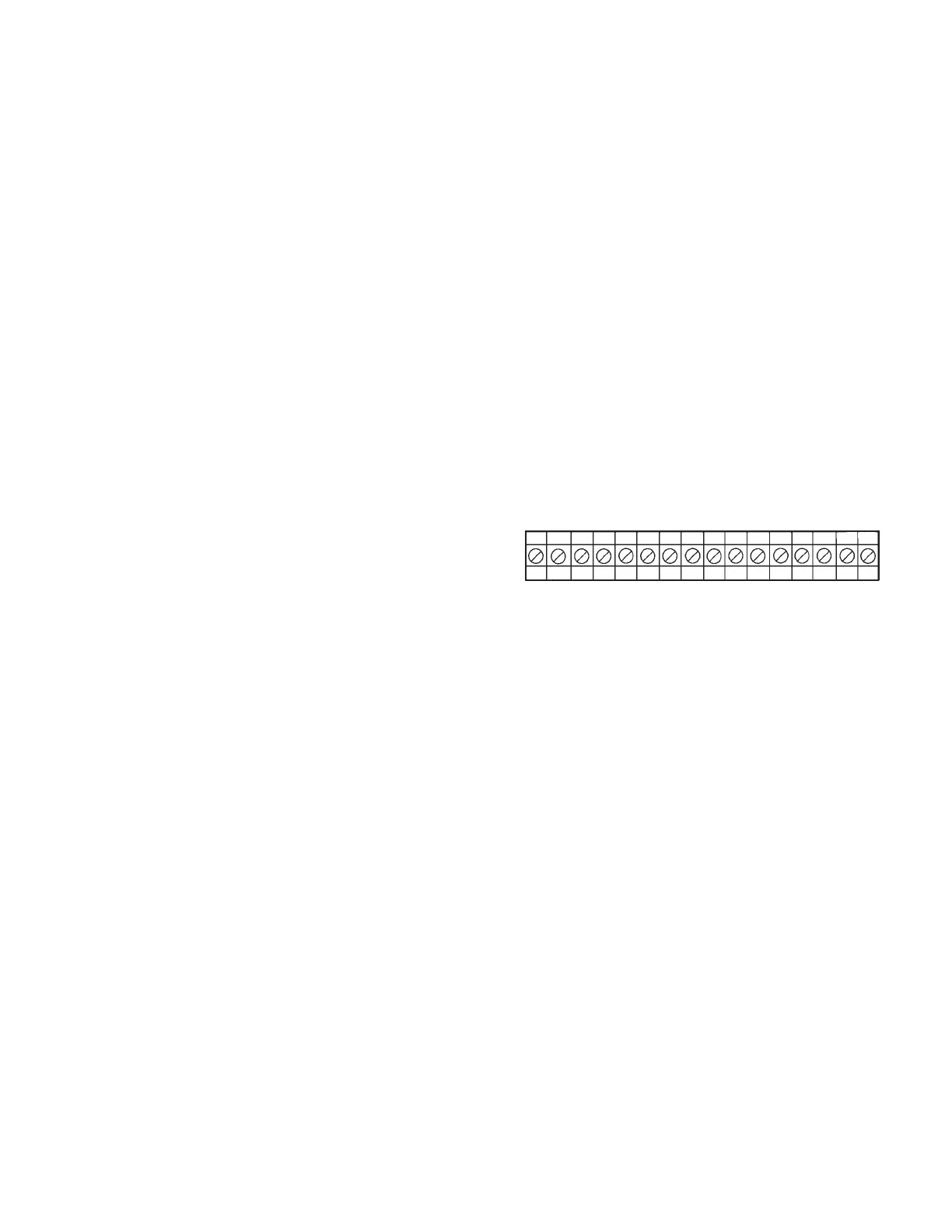
Terminal Block (see Figure 16)
• Terminal connections are sized for 12 - 24 AWG
• Terminal is labeled from left to right, No. 1 through No. 16
• The terminals are designed as follows:
1. Not Used
2. Not Used
3. + Detection Input
4. – Detection Input
5. Initiating Input Circuit No. 2 (+)
6. Initiating Input Circuit No. 2 (–)
7. + Release Output
8. – Release Output
9. Not Used
10. Not Used
11. Not Used
12. Not Used
13. Not Used
14. Shutdown N.O.
15. Shutdown Common
16. Shutdown N.C.
FIGURE 16
004446
USER INTERFACE
2012-MAY-18 REV. 02 PAGE 7
CHECKFIRE MP-N Electric
Detection and Actuation System Manual
12345678 910111213141516
+–+–+– NOCNC

 Loading...