INSTALLATION
Before installing the detection and actuation system, the System
Planning portion of this manual should have been reviewed for
particular application resulting in a system layout sketch. Always
read the procedure before installing each component to become
familiar with the correct installation steps as they apply to the
particular application and sketch.
NOTICE
For ease of installation, the fire suppression
system should be installed before the detection
and actuation system.
INSTALLATION MATERIALS
All hardware and tools should be on hand before beginning the
installation. Check the Component Index, Page 37, to make
certain all necessary system components are available.
Material to be supplied by the installer includes:
– Ample cable ties or 1/4 in. (6 mm) clamps to guide and support
the detection wire.
– Non-wire braid hose (1/4 in.) to be used as a protective cover-
ing for the detection or power wire at points of securement and
when passing through bulkheads.
– Actuation line (1/4 in. hydraulic hose) and fittings to connect the
electric detection and actuation system actuator to the fire
suppression system. (See applicable ANSUL Fire Suppression
Systems installation manual for additional details.)
Tools required to perform the installation include:
– Drill and Drill Bit Set (or welding equipment)
– 1/8 in. Blade Screwdriver
– 1/4 in. Blade Screwdriver
– Phillips Screwdriver
– Standard Sidecutters
– Small Sidecutters (1/4 in. cut)
– Wire Stripper
– Low Wattage Soldering Pencil (35 watt)
– Rosin Core Solder (60/40)
– Rubberized Electricianʼs Tape
MOUNTING BRACKET INSTALLATION
Three mounting bracket options are available:
• Mounting control module and pneumatic actuator on same
bracket
• Separate brackets for control module and pneumatic actuator
• Control module retrofit bracket to existing CHECKFIRE MP
bracket
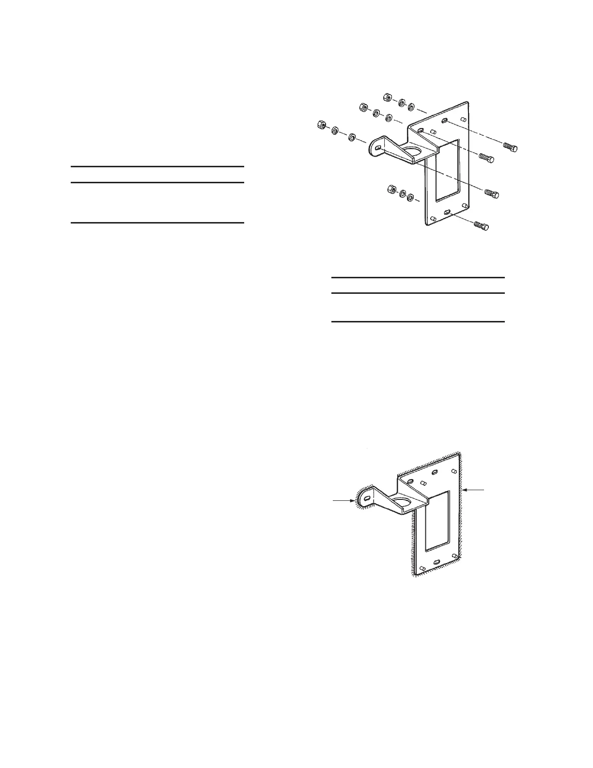
Bolting
1. Using the bracket as a template, carefully mark the location of
the bracket mounting holes.
2. Center punch the premarked hole locations and drill 3/8 in.
(10 mm) holes through the mounting surface.
3. Secure the bracket to the mounting surface using appropriate
length of 5/16 in. (8 mm) bolts with flat washers, lockwashers,
and nuts. See Figure 19.
FIGURE 19
002761
Welding
NOTICE
Never weld on the vehicle frame without first
consulting the owner and vehicle manufacturer.
1. Carefully mark the location of the bracket.
2. Clean the mounting bracket and mounting surface using a
wire brush until clean steel surfaces are available for welding.
3. Secure the bracket to the mounting surface using 1/8 in.
(3 mm) fillet welds at the top, bottom, and both sides. See
Figure 20.
4. Remove all weld spatter from the bracket and mounting
surface.
5. Prime and paint the exposed bare metal of the bracket and
mounting surface.
FIGURE 20
002762
INSTALLATION
PAGE 12 REV. 02 2012-MAY-18
CHECKFIRE MP-N Electric
Detection and Actuation System Manual
WELD
WELD

 Loading...