RELEASE CIRCUIT TEST MODULE INSTRUCTIONS
FIGURE 52
003016
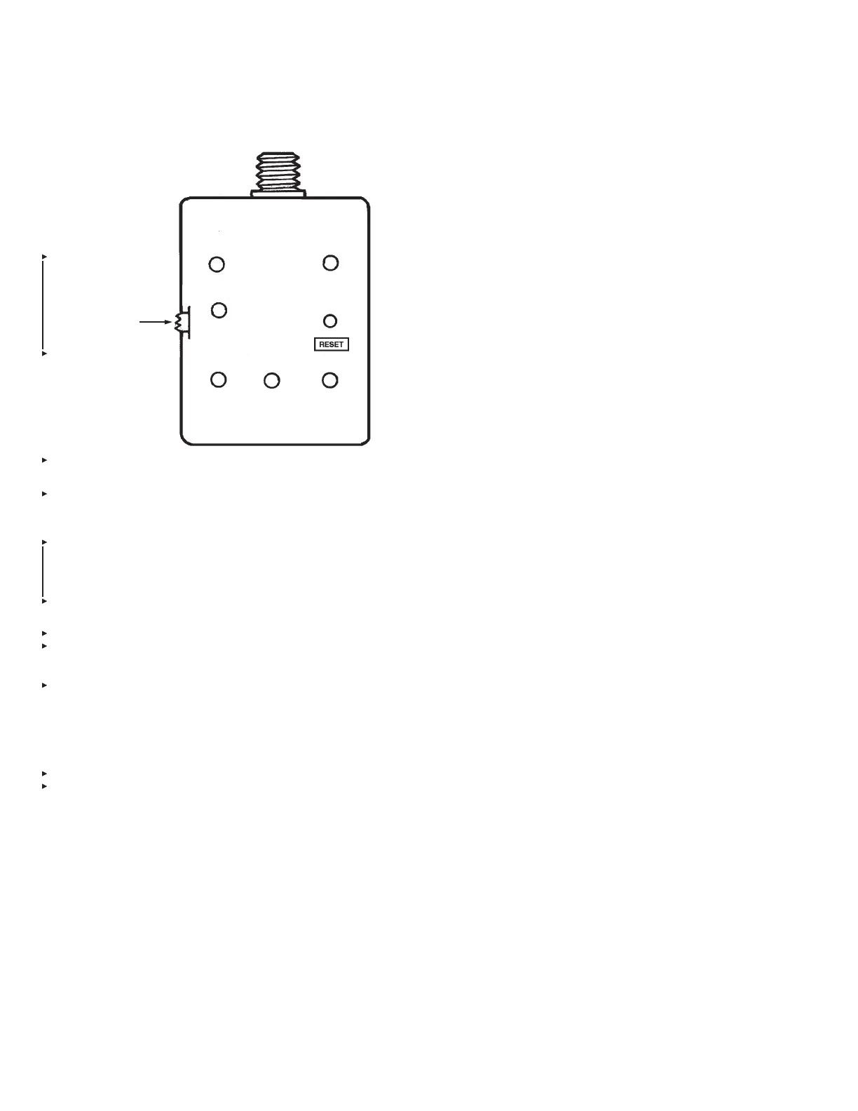
Operation is as follows (see Figure 52):
1. The receptable on the tester mates with the connector on the
gas motor actuation cable, Part No. 416129, used with the
CHECKFIRE MP-N. Note: The Release Circuit Test Module is
shipped with a Test Adapter, Part No. 436243, provided for
testing units with PAD Connector/Cable Assembly, Part No.
436114, or PAD Cable Assembly 20 ft (6.1 m), Part No.
436242. Not required for MP-N.
2. A three-position slide switch is located on the side of the
enclosure to select the type of release circuit to test (MP-N or
SC-N) and the middle position is “OFF.”
3. Steps for operation are:
a. With slide switch, select type of release circuit to be tested.
This will also turn the unit on.
b. Press the reset button on the tester. This will illuminate the
“READY LED” if it is not already illuminated.
c. Connect to control unit actuator cable.
d. Proceed with activating output. (Refer to Function Test,
Page 21, in the Installation Section.)
e. Once the unit activates, the unit tester will indicate a
“PASS” or “FAIL” status resulting from the test.
f. The tester can then be reset by pressing the RESET
button, which will prepare it for the next test.
APPENDIX
PAGE 36 REV. 02 2012-MAY-18
CHECKFIRE MP-N Electric
Detection and Actuation System Manual
SWITCH:
MP-N
OFF
SC-N
MP
MP-N
SC
SC-N
PASS FAIL READY
BATTERY
LOW

 Loading...