INSTALLATION
/ 17
Gas connection
Make sure, using the labels on the packaging and the data
plate on the appliance itself, that the boiler is in the correct
country and that the gas category for which the boiler was
designed corresponds to one of the categories available in the
country where it will be used.
The gas supply piping must be created and measured out in
compliance with specic legal requirements and in accordance
with the maximum power of the boiler.
Check that the supplied gas corresponds to the type of gas for
which the boiler was designed (see the data plate located on
the appliance itself).
It is also important to check that the pressure of the gas
(methane or LPG) you will be using to feed the boiler is
suitable, because if it is insufcient the power may be reduced,
causing inconvenience for the user.
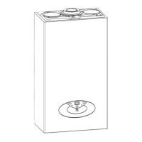
Water connection
The illustration below shows the connections for the water and
gas attachments of the boiler. See valves conguration on
page 13.
Check that the maximum water mains pressure does not
exceed 6 bar; if it does, a pressure reducing valve must be
installed.
For the measuring of the pipes and of the heating bodies in the
heating system, the residual head value should be calculated
as a function of the requested ow rate, in accordance with the
values shown in the circulation pump graph.
Legend:
A. Central heating Flow
B. Domestic Hot Water Outlet
C. Gas Inlet
D. Domestic Cold Water Inlet
E. Central Heating Return
F. Safety Valve Discharge
H. Drain Valve
I. Condensate discharge
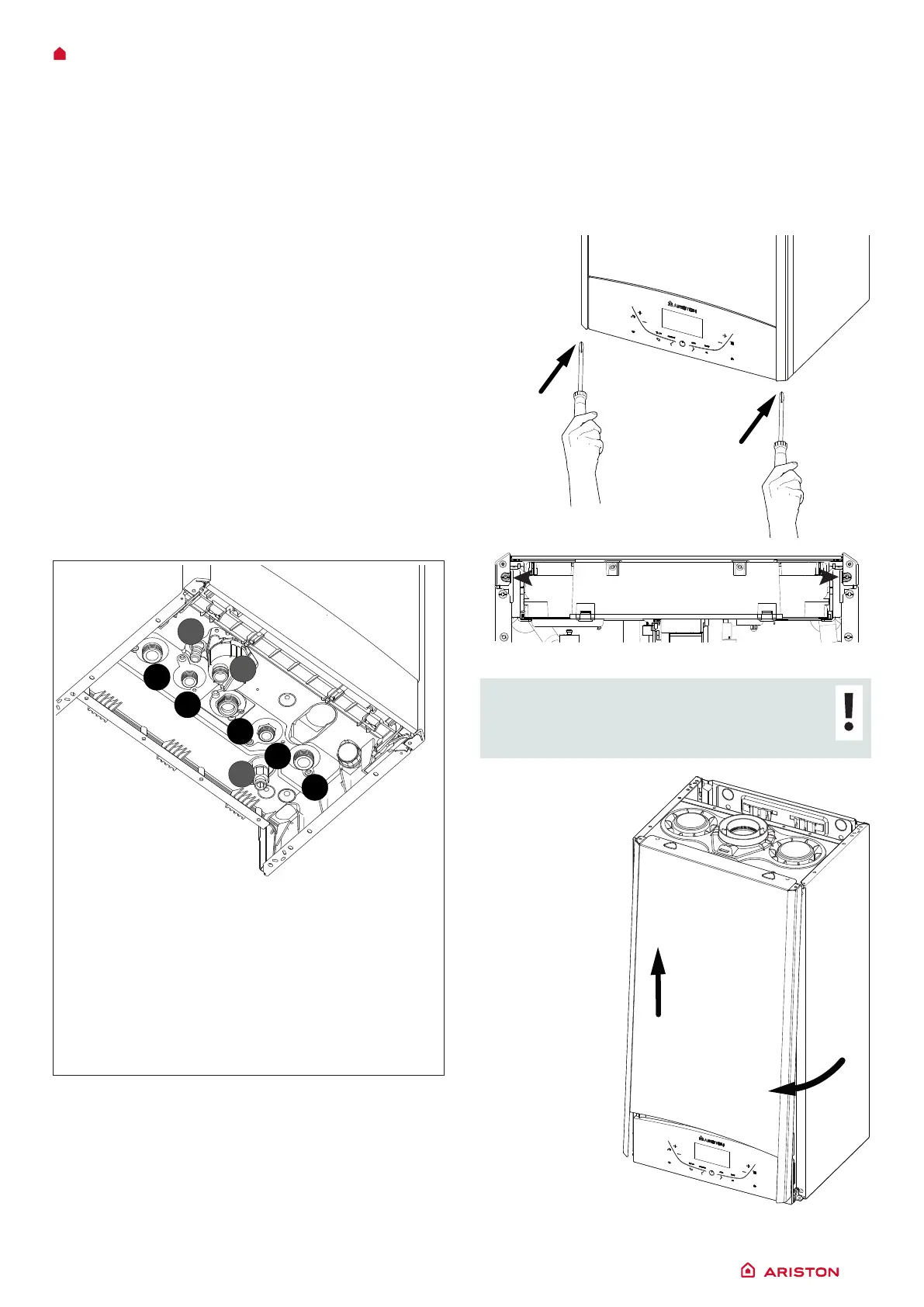
Instructions for removing the housing and inspecting the
appliance.
Before carrying out any work on the boiler, switch off the power
supply using the and close the gas tap.
To access the inside of the boiler:
- unscrew the two screws from the front panel (a), pull the panel
forwards and uncouple it from the upper pins (b),
- pivot the electronic unit by pulling it forwards (c).
(a)
CAUTION!!
REMOVE ONLY THE SCREWS SHOWN
IN THE PICTURE
(b)
A
B
C
D
H
F
I
E
 Loading...