INSTALLATION
/ 22
Fitting the Coaxial Flue
(Ø 60 / 100 Horizontal)
Contents:
1x Silicone O-Ring (60mm)
1x Elbow (90°)
2x Wall Seals (Internal & External)
1x Flue Pipe including Terminal (1 metre - 60/100)
2x Flue Clamps
4x Screws
2x Seals
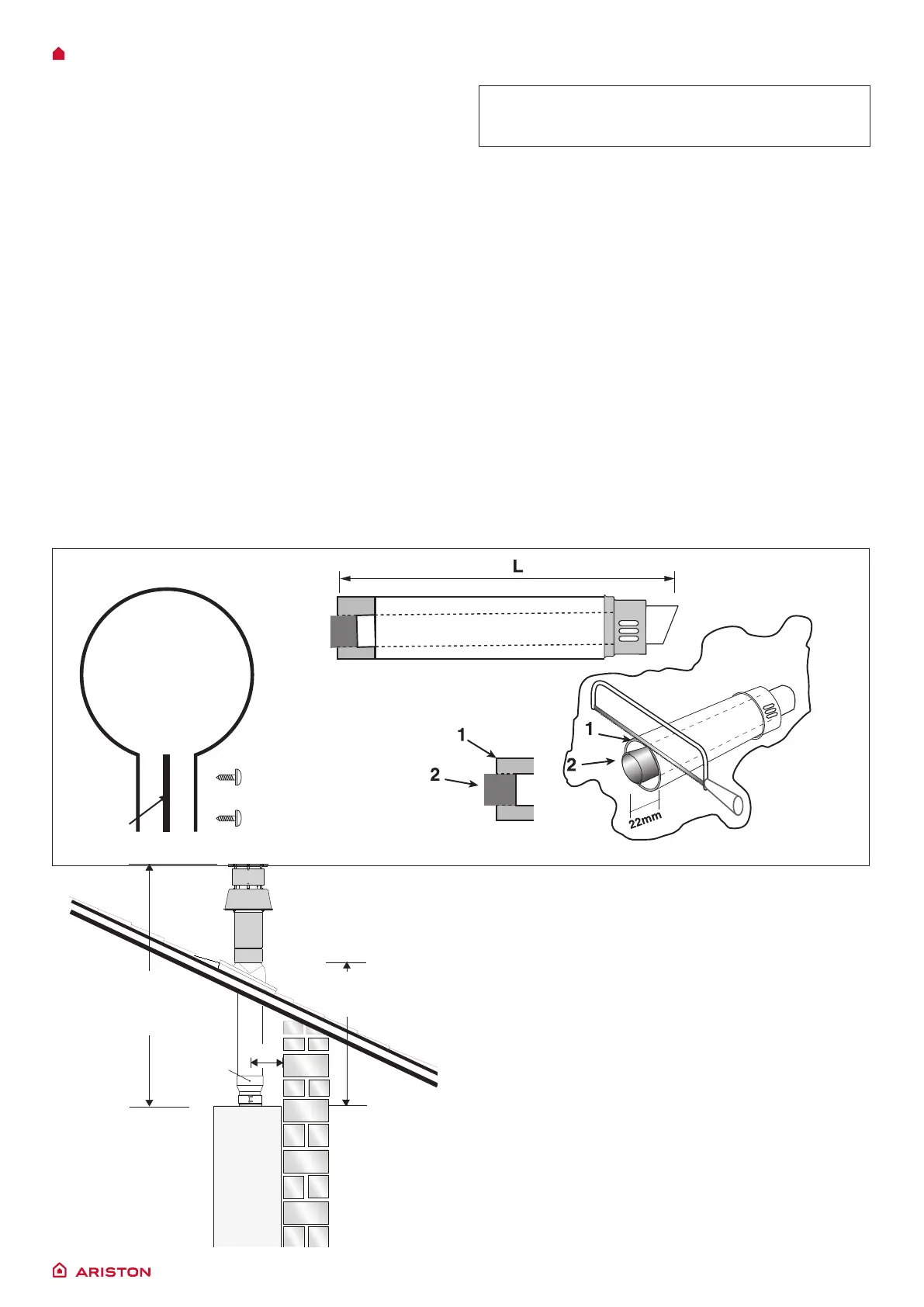
Once the boiler has been positioned on the wall, t the rubber
ue seal into the internal ue turret (see diagram opposite),
Insert the elbow into the socket and rotate to the required
position. note: It is possible to rotate the elbow 360° on its
vertical axis.
Using the ue clamp, seals and screws supplied (Fig 4) secure
the elbow to the boiler.
The 1 metre horizontal ue kit (3318073) supplied is suitable for
an exact X dimension of 753mm.
Measure the distance from the face of the external wall to
the face of the ue elbow (X - Fig 2), this gure must now be
subtracted from 753mm, you now have the total amount to be
cut from the plain end of the ue.
Draw a circle around the outer ue and cut the ue to the
required length taking care not to cut the inner ue, next cut
the inner ue ensuring that the length between the inner and
outer ue is maintained. (Fig 4).
e.g.
X = 555mm
753-555 = 198mm (Length to be cut from the plain end of the
ue).
Once cut to the required length, ensure that the ue is free
from burrs and reassemble the ue. If tting the ue from inside
of the building attach the outer wall seal to the ue terminal
and push the ue through the hole, once the wall seal has
passed through the hole, pull the ue back until the seal is
ush with the wall. Alternatively, the ue can be installed from
outside of the building, the outer seal being tted last.
Should the ue require extending, the ue connections are
push t, however, one ue bracket should be used to secure
each metre of ue.
Note: See table for maximum and minimum ue runs.
Note: A Plume management kit is available for 60/100
horizontal termination. Instructions for installation are
supplied with the Plume management kit.
Fitting the 5” Flue
(Ø 80 / 125 Horizontal/vertical)
Once the boiler has been positioned on the wall, it is necessary
to insert the Ø80/125 adaptor (Fig. 5) for both horizontal and
vertical ue runs into the boiler ue socket (not supplied with
ue kit - Part No 3318095).
Push the adaptor onto the boilers ue connection, grease the
seals then add extensions or elbows as required, secure the
adaptor, using the clamp and screws provided.
To t extensions or elbows it is rst necessary to ensure that
the lip seal is tted correctly into the inner ue, once veried,
it is simply necessary to push them together, no clamps are
necessary to secure the ue components.
180 mm
Total length
of Vertical Kit
1240 mm
5" Adaptor
Part no: 3318095
* This length will vary
according to the type
of ashing installed
Useable length
of Vertical ue
575 mm*
Fig. 5
Clamp
Seal
Screws
Fig. 4
 Loading...