INSTALLATION
/ 29
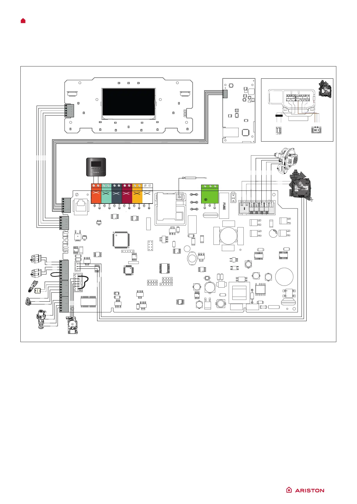
Electrical diagram
For increased safety, ask a qualied technician to perform a thorough check of the electrical system.
The manufacturer is not responsible for any damage caused by the lack of a suitable earthing system or by the malfunctioning of the
electricity mains supply.
CN20
CN17
CN23
CN16
CN21
CN22
CN15
CN13
CN14
CN10
CN7
CN9
GATEWAY WIFI
BUS
T B
FLOOR
TA2
230 V
SE TNK SOL TA1
230 V
230 V 230 V 230 V 230 V
N L
MADE IN ITALY
MADE IN ITALY
Bk
Bk
CN16
CN9
21 32
1
2
2
1
1
3
Bk
Bl
Br
Bl
Wh
Rd
Bk
Bk
Br
Br
Bl
Bk
Bk
Bk
Bl
Bl
Bk
Br
Rd
Bk
1
1
11
1
1
1
1
1
1
CN1
CUBE
ALTEAS ONE+ NET
1
2
3
4
5
6
8
9
10
Bk= Black
Rd = Red
Gr = Green
Bl = Blue
Br = Brown
Wh = White
Gry = Grey
1. Central Heating Return Temperature Probe
2. Central Heating Flow Temperature Probe
3. D.H.W. Flow Switch
4. Water pressure sensor
5. Diverter valve
6. Gas Valve
7. Modulating Circulation Pump with air release valve
8. Modulating Fan
9. Detection/Ignition electrode
10 Spark generator
 Loading...