INSTALLATION
/ 19
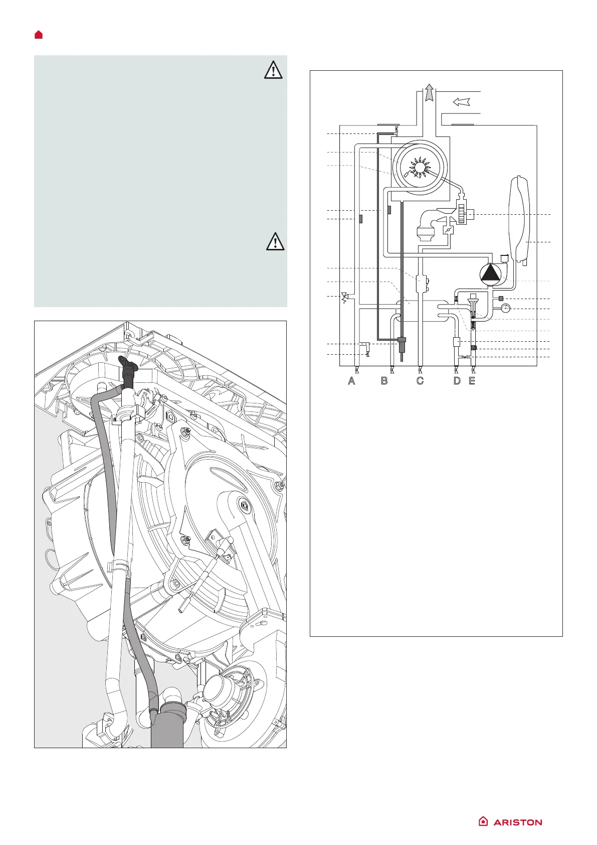
Water circuit diagram
1. Air relief valve
3. Main Heat Exchanger
4. Detection/Ignition electrode
5. Central Heating Return Temperature Probe
6. Central Heating Flow Temperature Probe
7. Gas Valve
8. Secondary Exchanger
9. Safety valve
11. Drain valve
10. Condensate Trap
12. Filling loop
13. Central Heating Filter
14. D.H.W. Flow Switch
15. Automatic By-pass
16. Diverter valve
17. Pressure Gauge
18. Water pressure sensor
19. Modulating Circulation Pump with air release
valve
20. Expansion Vessel
21. Modulating Fan
BEFORE THE DEVICE IS USED, FOR
THE FIRST TIME THE TRAP MUST BE
FILLED WITH WATER.
The siphon is lled with water during
deaeration procedure of the boiler (or
heating system) - see p. 30
Ensure that the siphon contains water; if not,
it must be relled. Open the manual air vent
(2) on the main exchanger until complete
lling. Check again the system pressure on
the pressure gauge.
WARNING!
INSUFFICIENT WATER IN THE
TRAP CAN TEMPORARILY CAUSE THE
FLUE GAS TO BE EXPELLED INTO THE
SURROUNDING AMBIENT AIR
A B C D E
13
14
16
15
18
17
19
20
1
4
3
9
10
8
7
5
6
12
21
11
 Loading...