26 /EN
AIR SUPPLY CONNECTIONS
WARNING!
A type of canalization not suitable aects product performance
and significantly increases the heating time!
Please bear in mind that using air from heated environments may
hamper the building’s thermal performance.
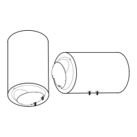
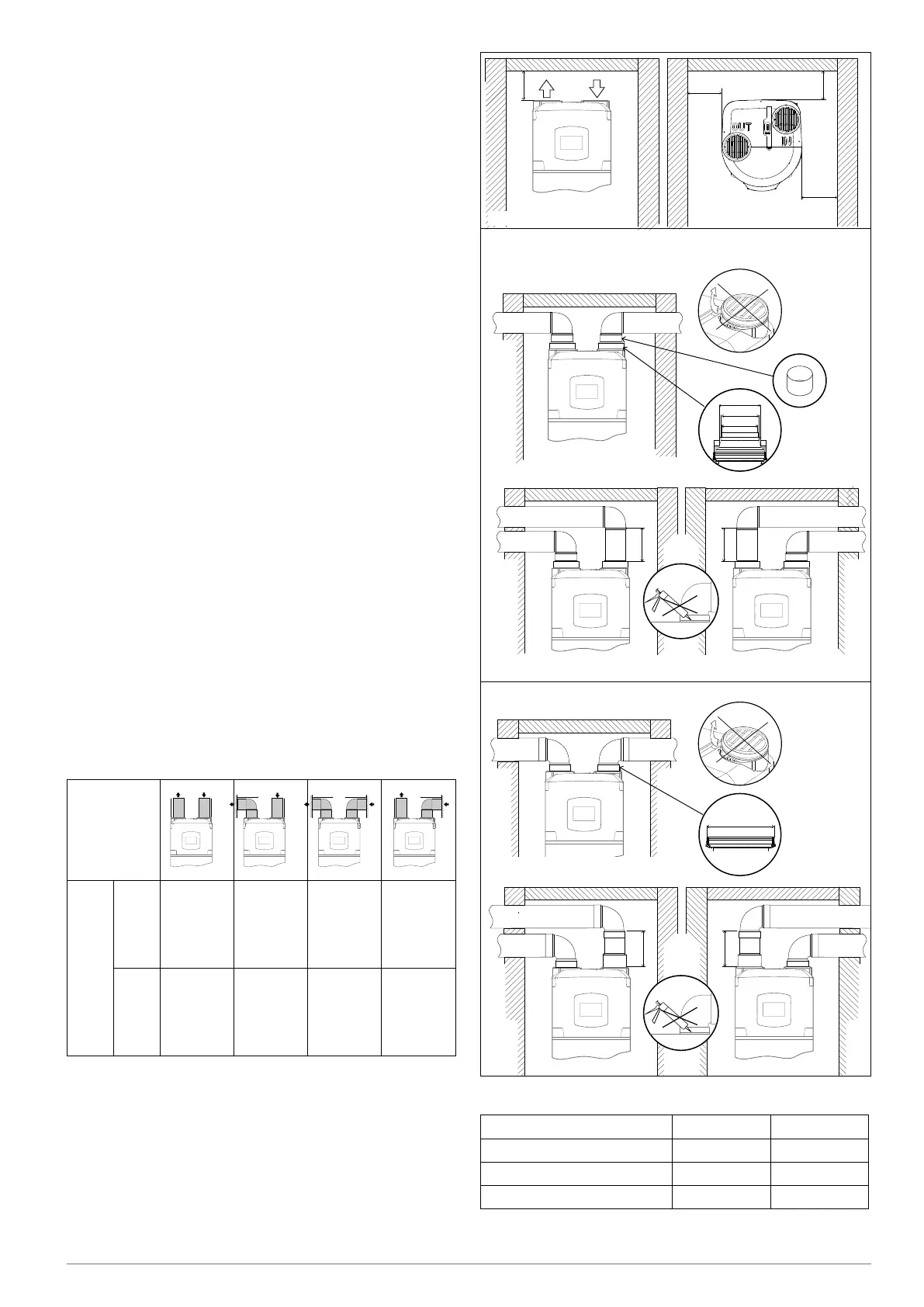
There is one connection for the air intake and one for the air exhaust
on the rear side of the appliance. Important: do not remove, break or
tamper in any way with the air inlet and outlet grilles (Fig. A).
The outlet air may reach temperatures that are 5-10°C lower com-
pared to that of the inlet air and, if not ducted, the temperature of the
room of installation may drop sensibly.
If operation by exhaust or intake to the outside (or another room) of
the treated air by the heat pump is foreseen, suitable ducting must
be used for air passage.
IMPORTANT: we recommend using insulated pipes to avoid the
formation of condensation.
Ensure that the ducting is connected and fastened securely to the
product to prevent accidental disconnections and annoying noises.
Install the ducts by following all the heights as shown in (Fig. B).
Leave a minimum distance between the product and the ducts to
allow for the removal of the evaporator filter.
WARNING: Do not use outdoor grills resulting in high losses, such
as anti-insect grilles.
The grids used
should allow good air flow, the distance between the inlet and outlet
air should not be less than 37cm. Protect pipes from the external
wind. The expulsion of air in the chimney is allowed only if the draft is
appropriate, is also required periodic maintenance of the barrel, and
chimney accessories.
For the maximum length of piping, including the terminal, please refer
to the “Typical Configurations” table.
The total static pressure loss due to installation is calculated by
adding the loss of the single installed components; this sum must
be lower than the static pressure of the fan (Appendix)
≥ 500
≥ 500
≥ 200
≥ 200
ø 150 ø 150
ø 200 ø 200
ø 200
ø 200
≥ 200
ø 200
ø 200
≥ 200
≥ 200
ø 150
ø 150
≥ 200
ø 150
ø 150
199,3
158,3
147,3
155,3
FIG. A
FIG. B
TYPICAL CONFIGURATIONS
Type
Maximum piping length
L1 exhaust +
L2 intake
ø150
(PVC)
22 [m] 19 [m] 16 [m] 19 [m]
ø160
(PEHD)
28 [m] 24 [m] 20 [m] 24 [m]
When a curve is added:
• 90° (PEHD) remove 4 m from the permitted length
• 45° (PEHD) remove 2 m from the permitted length
• 90° (PVC) remove 3 m from the permitted length
• 45° (PVC) remove 1.5 m from the permitted length
L1 L1L2 L2
Model 200 l 250 l
ø 150 mm ≥2050 mm ≥2310 mm
ø 160 mm (PEHD) ≥2140 mm ≥2400 mm
ø 200 mm ≥2060 mm ≥2320 mm
Table with minimum ceiling heights for ducted installation
 Loading...