P/N 146550999-1-ML • REV Q • ISS 07APR21 5 / 42
Figure 11
(1) Alarm relay
(2) Alarm zone
(3) Tamper switch output
Ra Alarm EOL resistor
Rt Tamper EOL resistor
Setting the detector
See Figure 14 for jumpers and DIP switch location.
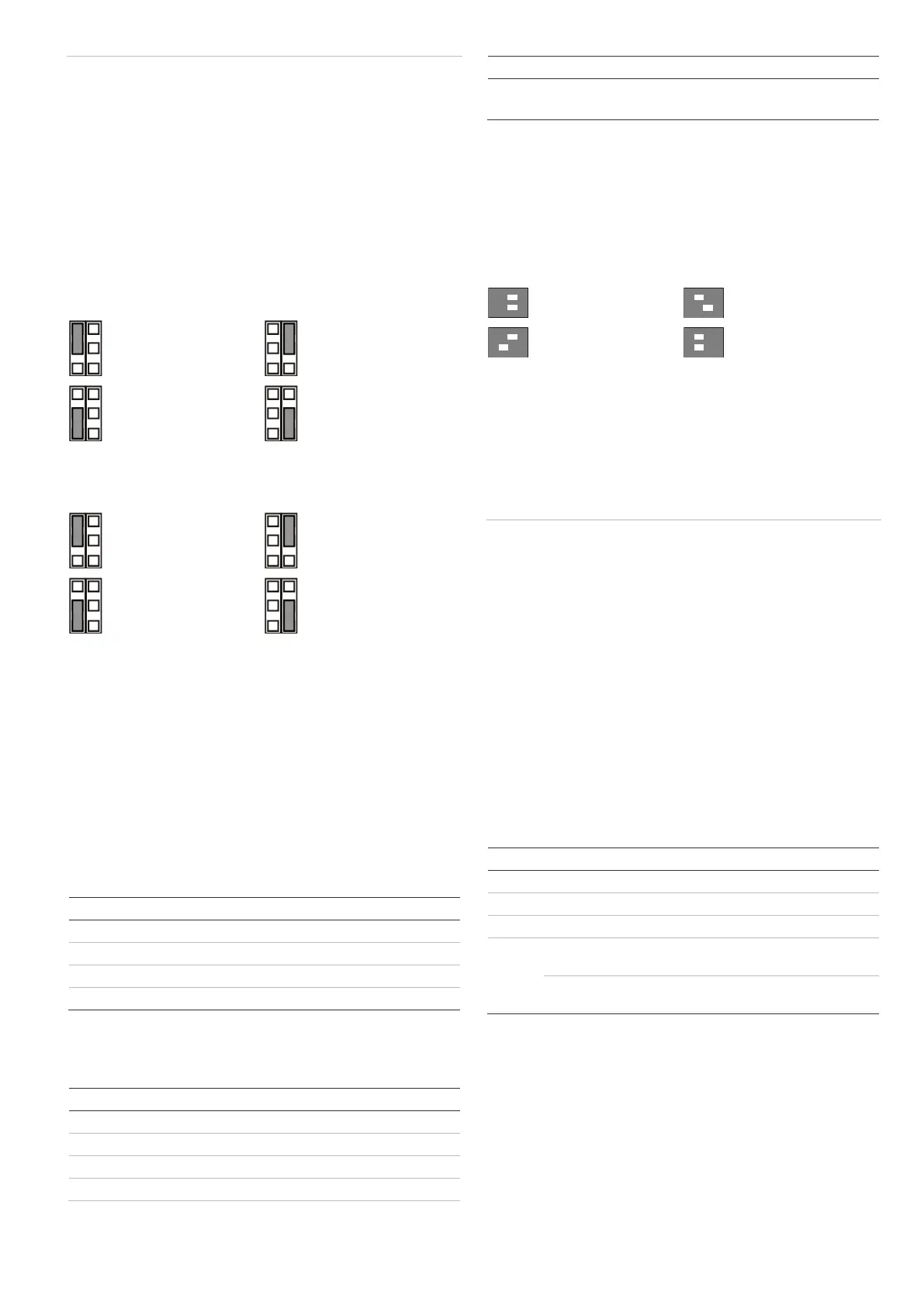
Jumpers
Jumpers set onboard EOL mode and value. The circuit is
shown in Figure 11.
JA: Set onboard alarm EOL resistor (Ra)
Off: No onboard alarm EOL.
JT: Set onboard tamper EOL resistor (Rt)
Off: No onboard tamper EOL.
Configuring the zone
To set up the zone, apply the following guidelines.
• Select appropriate EOL resistor values with JA and JT.
For example, setting of jumper JT determines Rt value.
• For isolated outputs remove JT.
• Remove jumpers JA and JT to exclude onboard EOL
values.
For a single zone with all onboard resistors set, the zone
resistance can be the following.
Table 2: Zone resistance values
DIP switches
Table 3: SW1, general settings
1 On, 2 On: 12 m (39 ft.)*
1 Off, 2 On: 9 m (30 ft.)
1 On, 2 Off: 6 m (20 ft.)
1 Off, 2 Off: 4 m (13 ft.)
* Factory default
DIP switch SW1
SW1-1, SW1-2: Radar range
Use SW1-1 and SW1-2 to set the radar range exactly to fit the
application. The radar is of a range-gating type which means
that the range of detection is very accurate.
12 m (40 ft.)
Factory default.
SW1-3: Polarity
On: Positive polarity. Configures the inputs (WT and D/N) as
“Active high”.
Off: Negative polarity. Configures the inputs (WT and D/N) as
“Active low”. Factory default.
The functionality is explained in Figure 10.
Figure 10
(1) Polarity high
(2) Polarity low
(3) Walk test
(4) Day/night
This function also depends on the SW1-5 setting. See “SW1-5:
Remote functionality” below.
SW1-4: Reserved
Do not change.
SW1-5: Remote functionality
On: Remote on. Enables WT and day/night inputs.
Off: Remote off. Disables WT and day/night inputs (factory
default).
The following functionality depends on the Remote setting.
Table 4: Functions dependent on the Remote setting
Enabled in day
mode with no WT
Enabled in day
mode with no WT
See also “Connections” on page 4.
SW1-6: LEDs
On: LEDs are enabled. See “LEDs and outputs” on page 6 for
LED functionality.
Off: LEDs are disabled for any state.
 Loading...