6 / 42 P/N 146550999-1-ML • REV Q • ISS 07APR21
Configuring the coverage pattern
• Remove blinders (Figures 8 and 9) if necessary. The
modified pattern is shown below blinder configuration.
Note: If both blinders are installed in DD1012(-D), the
detector range is limited to 6 m (default) .
• In case of DD1012(-D), modify the pattern by breaking out
blinder parts (shown as gray in Figure 8, item 1). The
corresponding curtain fragments are shown in Figure 8,
item 2.
• Put the appropriate mirror stickers if necessary. See
Figure 7, item 1 for details.
Caution: Removing stickers can damage the mirror
surface.
• When near objects directly under the detector, fit the mask
to the inside of the window (default). This disables the part
of the curtains looking down at the object, whose
closeness might destabilize the detector. See Figure 7,
item 2.
Walk testing the detector
There are two ways for switching on the walk test mode.
SW1-6 set to LED on, SW1-5 set to Remote off
In this mode the LED indication is always enabled (constant
walk test mode).
SW1-6 set to LED on, SW1-5 set to Remote on
This setting enables the walk test input (pin 7) and the
day/night input (pin 8). This allows the user to activate LED
indication remotely by setting the detector into the day mode
and activate the walk test.
Green mode
When SW1-5 is set to Remote on, the radar is switched off
during the day mode (with no WT) to reduce current
consumption. The detector is then operating in PIR only mode.
Note: The Day/night line must be connected to the control
panel for this mode to work.
Alarm memory
When SW1-5 is set to Remote on, alarms that occurred during
the night mode are stored in the detector memory. They are
indicated by flashing red LED when the unit switches to day
mode (walk test disabled). The memory is cleared when the
detector switches back to the night mode.
Note: Set SW1-6 to Off to prevent showing the alarm memory
on the LEDs. See “SW1-6: LEDs” on page 5.
LEDs and outputs
To enable LEDs functionality, set SW1-6 to On, otherwise
LEDs are disabled in any condition. See “SW1-6: LEDs” on
page 5 for more details.
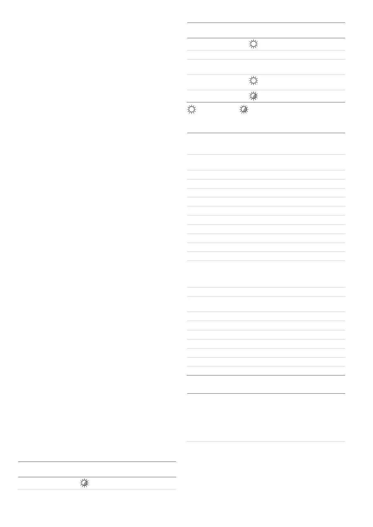
Table 5: LEDs and outputs
 Loading...