2 Aruba Instant On AP11 Access Point | Installation Guide
LED
The AP11 access point has two LEDs that indicate the system and radio status of the device.
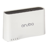
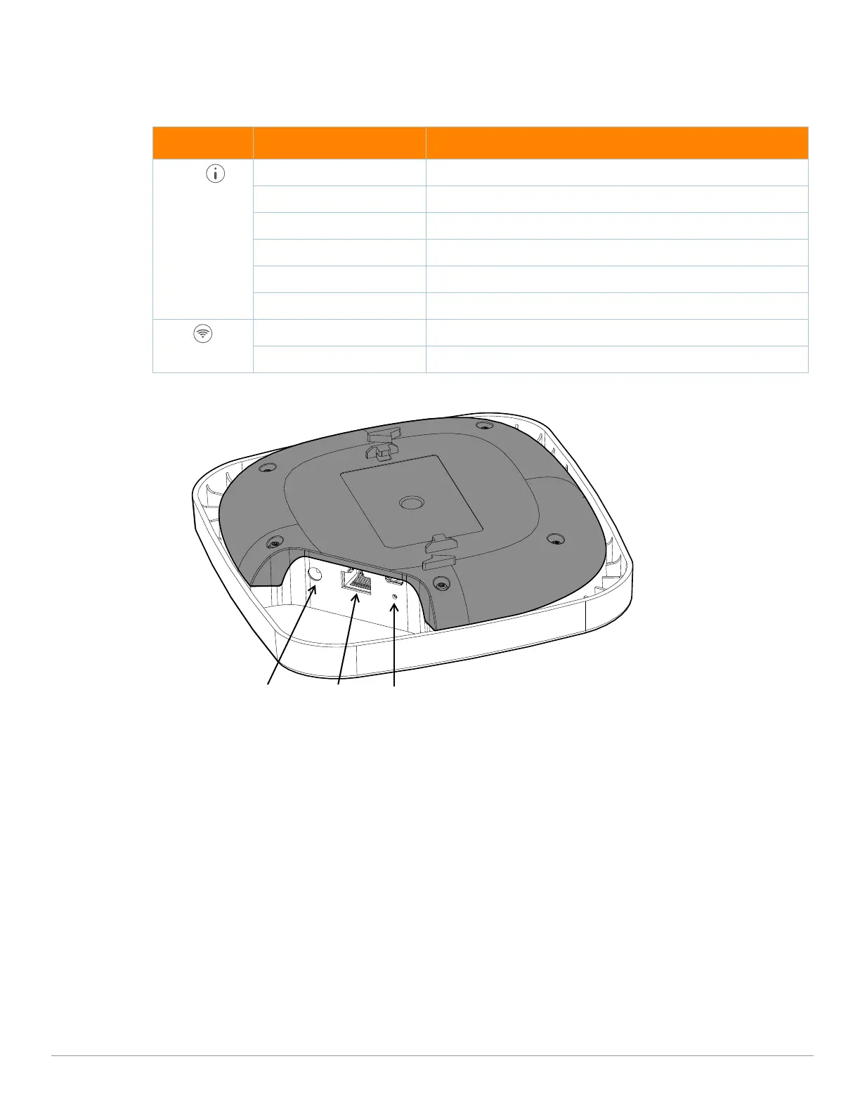
Figure 2 AP11 (rear view)
E0/POE Port
The AP11 access point is equipped with one 10/100/1000Base-T auto-sensing, MDI/MDX Ethernet port (E0) for
wired network connectivity. This port supports IEEE 802.3af Power over Ethernet (PoE), accepting 48Vdc
(nominal) as a standard defined Powered Device (PD) from a Power Sourcing Equipment (PSE) such as a PoE
midspan injector, or network infrastructure that supports PoE.
DC Power Socket
If PoE is not available, a proprietary Aruba 12V/30W power adapter can be used to power the AP11 access point.
This power adapter is available in the box if you buy the AP11 and power adapter bundle.
Additionally, a locally-sourced AC-to-DC adapter (or any DC source) can be used to power this device, as long as it
complies with all applicable local regulatory requirements and the DC interface meets the following
specifications:
12 Vdc (+/- 5%) and at least 12W
2.1/5.5 mm center-positive circular plug, 9.5 mm length
Table 1 AP11 Access Point LEDs Status
LED Color/State Meaning
System No Lights Device has no power
Blinking
Green Device is starting
Alternating Green/Amber Device is ready for setup
Solid Green Device is ready
Solid Amber Device has detected a problem
Solid Red Device has an issue- immediate action required
Radio No Lights Wi-Fi is not ready, wireless clients cannot connect
Solid Green Wi-Fi is ready, wireless clients can connect
DC Power Socket E0/POE Reset
 Loading...