1-8
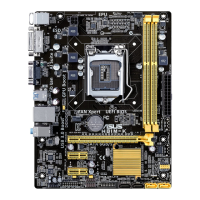
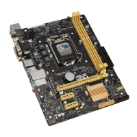
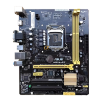
Chapter 1: Product introduction
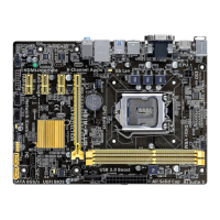
ADIMMiskeyedwithanotchsothatittsinonlyonedirection.DONOTforceaDIMMinto
asocketinthewrongdirectiontoavoiddamagingtheDIMM.
UnplugthepowersupplybeforeaddingorremovingDIMMsorothersystemcomponents.
Failuretodosocancauseseveredamagetoboththemotherboardandthecomponents.
• ThedefaultmemoryoperationfrequencyisdependentonitsSerialPresenceDetect
(SPD),whichisthestandardwayofaccessinginformationfromamemorymodule.
Underthedefaultstate,somememorymodulesforoverclockingmayoperateata
lowerfrequencythanthevendor-markedvalue.Tooperateatthevendor-marked
oratahigherfrequency,refertosection2.5 Ai Tweaker menu for manual memory
frequencyadjustment.
• Forsystemstability,useamoreefcientmemorycoolingsystemtosupportafull
memoryload(2DIMMs)oroverclockingcondition.
• VisittheASUSwebsiteat:www.asus.comforthelatestQVL.
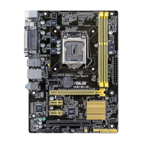
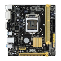
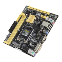
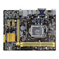
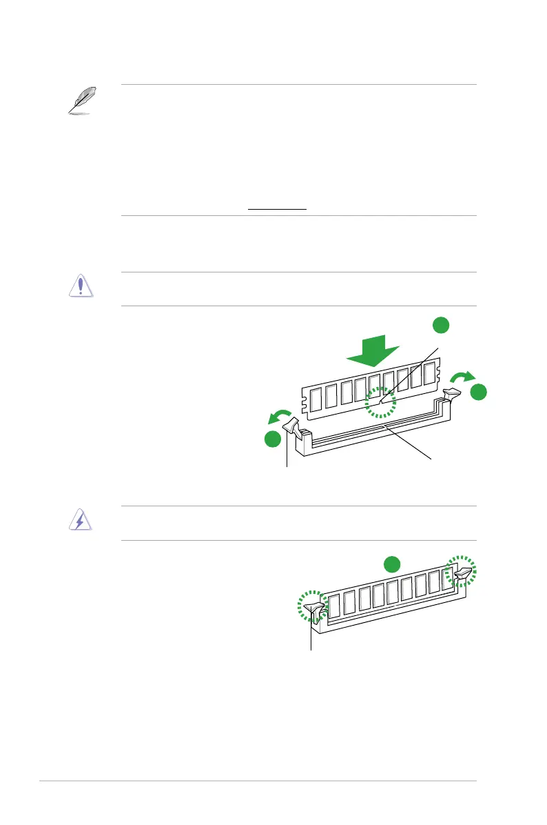
1.4.3 Installing a DIMM
1. Press the retaining clips
outwardtounlockaDIMM
socket.
2. AlignaDIMMonthesocket
such that the notch on the
DIMMmatchestheDIMM
slot key on the socket.
3. FirmlyinserttheDIMMintothe
socket until the retaining clips snap
backinplaceandtheDIMMis
properly seated.
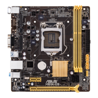
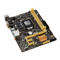
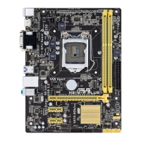
1.4.4 Removing a DIMM
To remove a DIMM:
1. SimultaneouslypresstheretainingclipsoutwardtounlocktheDIMM.
Unlocked retaining clip
1
DIMM notch
2
1
DIMM slot key
Locked Retaining Clip
3
 Loading...