29
Example:
An iS24 with a
concentric ue gas system
ø60/100mm has according
to the table a maximum ue
straight length of 13m In the
system that is going to be put
in there are 2 x 45° bends, so
the maximum ue gas length
is 13 – ( 2 x -1.0 ) = 11 m.
ø60/100mm
L
in m
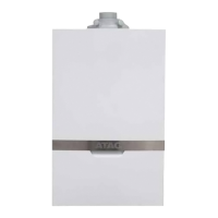
iS 12 Maximum straight length 60/100 13
iS 15 87° bend resistance length 1.6
iS 18 45° bend resistance length 1.0
iS 24
iS 32 Maximum straight length 60/100 6
iS 40 87° bend resistance length 1.6
45° bend resistance length 1.0
Concentric flue system ø60/100mm
Dimensions ue gas system and air supply system Table 9.8.2.a
L
9.8.2 Dimensioning of the ue gas and air intake duct
The total length of the run of the ue is determined by the ue diameter, including for the connection pipe,
elbows ttings and terminal covers etc..
An incorrect dimensioned ue system can lead to disorders. Look at table 9.8.2.a for the choice of the boiler
and the corresponding maximum ue lenght.
Explanation table 9.8.2.a:
Concentric ue gas system:
maximum noted length L = distance between boiler (from elbow or vertical adapter) and the end of terminal
When using bends the noted value behind every bend should be deducted from the maximum straight
length.
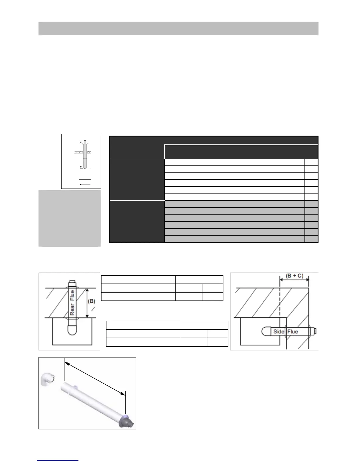
Flue dimensions
Rear Flue B (mm)
Min Max
Telescopic ue (FA100100) 280 430
Side Flue B + C (mm)
Min Max
Telescopic ue (FA100100) 285 435
Rear Flue
L = wall thickness (B) + 150mm
Side Flue
L = wall thickness (B) + distance between boiler and wall (C) + 150mm
If the length L is more than 580mm rear ue or 585mm side ue, then a
Horizontal ue xed length 1000mm (60/100mm) with lock function elbow
(FA100250) will need to be used instead, up to 810mm.
L
Figure 9.8.2.a
 Loading...