47
15.2 Checking ue integrity
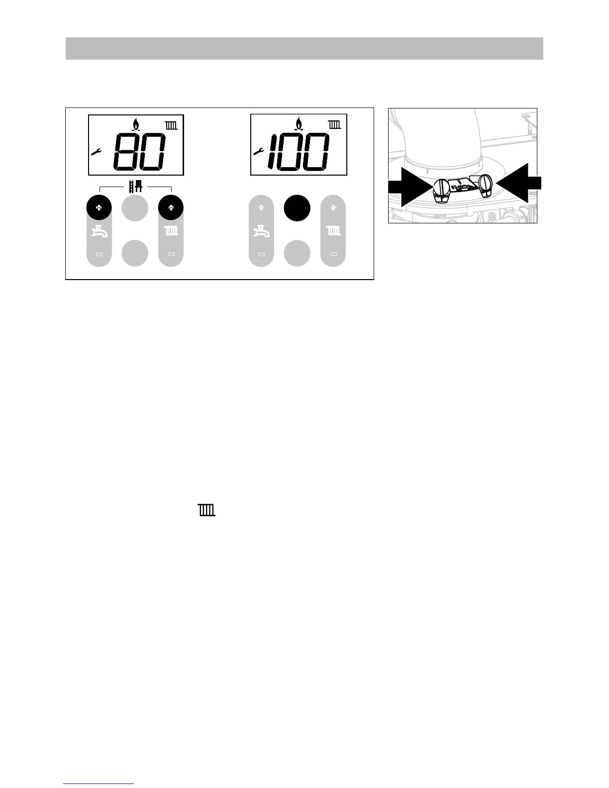
The integrity of the ue system and performance of the boiler can be checked via the ue turret sample
points shown in diagram 15.2.a.
The case must be on the boiler and the boiler made to run at maximum output.
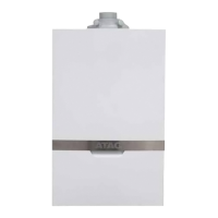
- Press both + buttons for 6 seconds (this will only give full CH output);
- When the ame symbol appears in the display press both + buttons again for 6 seconds;
- The display shows the supply water temperature ( appears in the display)
The boiler will switch to maximum power output of the boiler
- Press 1x the eco- button;
The display shows XX% (heating capacity)
- Insert the analyser probe into the air intake sample point 'B'.
- Ensure the probe reaches into the ow of air in air intake sample point. Ensure the sealing cone on the
probe is sealed to the sample point and correctly position the end of the probe.
- Allow the readings to stabilise and check that:
- O
2
is equal to, or greater than 20.6%.
- CO
2
is less than 0.2%
- If the readings are outside these limits then this indicates that there is a problem with the ue system or
combustion circuit, e.g. missing or dislodged seals.
End of measuring:
- Press the ESC button (
button).
The device switches o.
The display shows for 2 seconds code 180 or 181.
This completes the procedure.
A – Flue gas sample point
B – Air intake sample point
Figure 15.2.a
A
6 sec.
 Loading...