INSTRUCTION MANUAL
2904 0108 04 5
3.3 Options
– If two or more filters are used in combination, build the filter
heads together by means of a serial connection in the correct
air flow direction and DD upstream of PD. An arrow for the air
flow direction is provided on the filter head.
– For wall mounting, a special set is available as option. Fit the
mounting bracets with bolts, washers and nuts to a solid
frame within easy reach, leaving sufficient space underneath
for maintenance and service.
– Quick couplings are available to make an easy connection of
the automatic drain valve possible.
3.3.1 Dual Pressure Transmitter
Option on the DD, DDp and PD filters (refer to figure 4).
The dual pressure transmitter of Atlas Copco is designed to moni-
tor gauge pressure and differential pressure over a DD, DDp or
PD filter. For each channel, pressure and pressure drop, a 4 to 20
mA signal is provided.
The dual pressure transmitter is mounted between the filter head
and the pressure gauge. It needs a 12 to 24 VDC input voltage
and generates 2 signals: one signal proportional with the pressure
drop over the filter and one signal proportional with the gauge
input pressure. These 4 to 20 mA signals can be used as input on
the Compressor Room Control (CRC box) or on a computer with
an analogue input converter (to RS232 or RS485 protocol) to
monitor and log the behaviour of the filter.
3.3.2 Electronic Drain EWD 50L
Option on the DD and PD filters (refer to figure 5).
The electronic drain EWD 50L is a zero-loss, electronically opera-
ted drain valve, specially designed to drain oil condensate. A sen-
sor senses the condensate level. If this level exceeds a preset
value, the drain waits for a fixed-programmed time, then a sole-
noid valve is activated and the condensate is discharged. When
all the condensate is discharged, the solenoid valve closes and
condensate is collected again. This way, the loss of air is reduced
to a minimum.
If the microcontroller registers a malfunction, the automatic drain
valve will automatically change to alarm mode. This alarm signal
can be relayed via a potential-free contact.
The EWD 50L has three operating voltages: 220V, 115V and 24V.
An extra electric wiring can be foreseen to connect the potential
free contacts and an external test button.
Remove the manual or automatic drain of the filter before instal-
ling the EWD 50L.
3.4 ISO 8573-1 norm
For new installations as well as for installations that have to be
made up-to-date, the ISO 8573-1 norm can be used. This norm
describes several quality classes and, depending on these
classes and applications, some proposals are given fulfilling this
norm.
The air quality to ISO 8573-1 is expressed as follows: class X.Y.Z,
where X, Y and Z are respectively the quality classes with regard
to dirt, water and oil.
A few examples are given in Fig. 1:
A......... General purpose protection
(air quality to ISO 8573-1: class 2.-.2)
B......... High-quality air with reduced dewpoint
(air quality to ISO 8573-1: class 1.4.1)
C......... General purpose protection and reduced oil concentration
(air quality to ISO 8573-1: class 1.-.1)
D......... High quality air with extremely low dewpoint
(air quality to ISO 8573-1: class 1.2.1)
The components shown in Fig. 1 are:
1 .... Compressor with aftercooler
2 .... DD filter
3 .... PD filter
4 .... QD filter (for critical applications)
5 .... DDp filter
6 .... FD refrigerant dryer
7 .... CD desiccant dryer
8 .... Compressor with integrated dryer
The ISO 8573-1 norm only concerns “Compressed
air for general use and does not deal with, or is not
applicable to, e.g. breathing air.
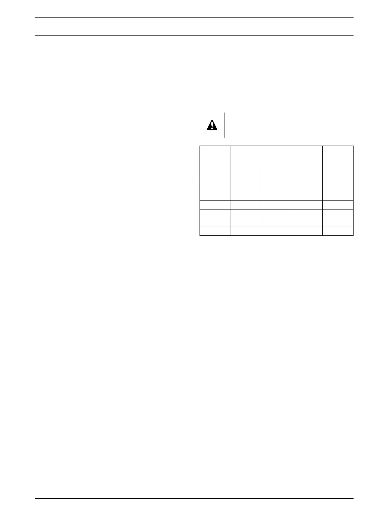
Quality class D
(Dirt)
W
(Water)
O
(Oil)
Max. particle
size
(µm)
Max.
concentration
(mg/m³)
Max. pressure
dewpoint
(°C)
Max.
concentration
(mg/m³)
1 0.1 0.1 -70 0.01
211-400.1
355-201.0
4158+35.0
5 4010+725
6––+10–
Vendor Manual Atlas Copco A090-070423-004 PD & DD Filters Instruction Manual
 Loading...