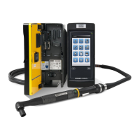
EBL Drives and Controllers EN EBL RE-Drive and EBL RE Module
© Atlas Copco Industrial Technique AB - 9836 5849 01
15
3 SET Input for Work Set signal. After the
time set for the Tool Disable Timer
1 elapses from input of the SET sig-
nal, the Operating Display LED
starts to light and the screwdriver
becomes operational. At the same
time the VALVE signal is gener-
ated.
4 GND Ground Terminal
5 +DC24V Output power for external equip-
ment. Max 0.2A
6 VALVE Enables solenoid valve control of
external devices such as jigs used
to hold the work piece in position.
7 BZ Output signal. Similar to the COMP
signal. Output is synchronized with
the Tool Disable Timer 2.
8 ER BZ Error signal. Generated if the SET
signal is interrupted. Output does
not stop until there is a reset or
when the last screw in the batch
have been tightened.
9 AC Inlet Power inlet (Only RE-
DRIVE)
Power inlet
10 Fuses (Only RE-DRIVE) Fuses and compartment for spare
fuses (T5A)
11 Drive connector (Only RE Module) Connect to EBL Drive / EBL Drive
Plus
Input Signals (SET, RESET)
The input method for the input signals of this equipment is a photo coupler input. The maximum input cur-
rent is 10 mA. To detect, input a minimum of 2 mA is required.
When connecting an open collector, connect the collector to the input terminal and the emitter to the +D-
C24V terminal.
Output Signals (COMP, VALVE, BZ, ER BZ)
The output signal type of this equipment is an open collector output.
The maximum rated load for each output terminal is 30V DC/80 mA. The maximum total current for
all output terminals is 200 mA. If this limit is exceeded damages to transistors can cause loss of com-
munication with PLC/FA computer.
If an output terminal is short circuited to 0V DC the maximum current is exceeded.
Do not apply voltage to the output terminals. For use of external equipment with relays or solenoid
valve coils, add a diode or equivalent to absorb reverse voltage.
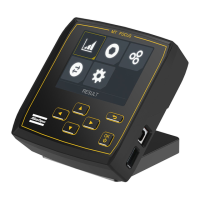
Settings
The function settings of the unit is performed by using the buttons F1, F2 and F3. Each button has a corre-
sponding seven-segment LED display.
 Loading...