20/06/2011 PM 9845 0512 02 Page 11 of 36
5.5. Typical flow
The compressor oil flow is controlled by two thermostatic bypass valves, ensuring reliable compressor operation and
optimum energy recovery.
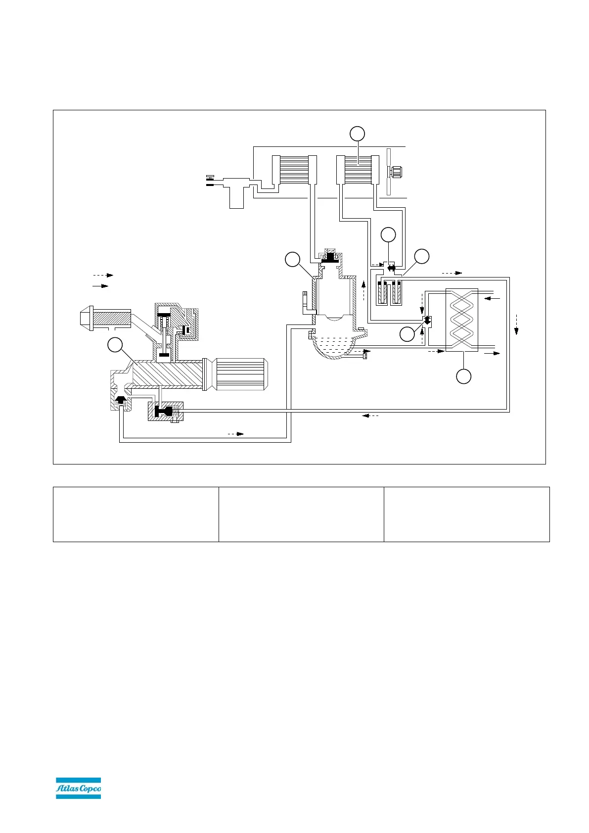
Figure 2: Example of air cooled oil injected screw compressor
7. 1
st
bypass valve of ER (BV1)
8. Heat exchanger of ER
12. Oil separator
14. 2
nd
bypass valve (BV2) of oil filter
pipe
23. Main oil cooler
24. Oil filter of oil filter pipe
25. Compressor element
The 1st bypass valve (Figure 2-7) is integrated in the ER unit and controls the operation of the oil heat exchanger (Figure 2-
8) of the ER unit. The 2nd bypass valve (Figure 2-14) is integrated in the oil filter pipe and controls the operation of the main
oil cooler (Figure 2-23) of the compressor. Both bypass valves consist of an insert (thermostat) mounted in a housing. In the
1st bypass valve of the ER unit, this is a single housing. In the 2nd bypass valve of the compressor, this housing is
integrated in the oil filter pipe (Figure 2-14).
 Loading...