20/06/2011 PM 9845 0512 02 Page 17 of 36
5.7. Electrical modifications & installation
11
+
-30 kW & 15-30 kW (VSD)
Please refer to the service diagram supplied with the main compressor and the additional service diagram 9845 1800 00 for
details about the electrical installation of the temperature sensors on the energy recovery unit.
The use of expansion module 1900 xxxx yy with connection cables varies for Mk 4 and Mk 5 and must be determined on
site.
30
+
-315 kW (& VSD)
NOTE: 90-315 kW is only available with Mk 4 controller.
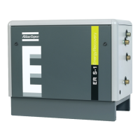
Figure 10: Electrical modifications to install the ER unit with Mk 4
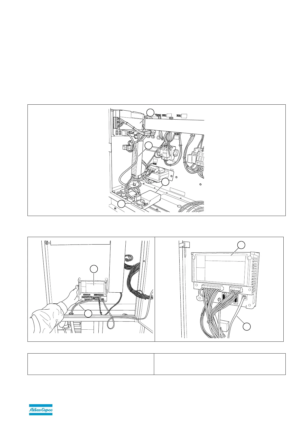
Figure 11: Electrical modifications to install the ER unit with Mk 5
4. Temperature sensor cables
5.
Expansion module
6. Link cable
7. Main controller module (Elektronikon)
The two temperature sensors (Figure 1-3&4) are connected using sensor cables (Figure 11-19) to an expansion module
(Figure 11-20) in the compressor cubicle. This expansion module is connected using a link cable (Figure 11-21) to the main
controller module (Elektronikon) (Figure 11-22).
 Loading...