20/06/2011 PM 9845 0512 02 Page 12 of 36
5.6. Mechanical modifications & installation
When servicing the unit, please follow the safety precautions as described in the instruction manual of the compressor.
Internal modifications
11
+
-30 kW range (& VSD)
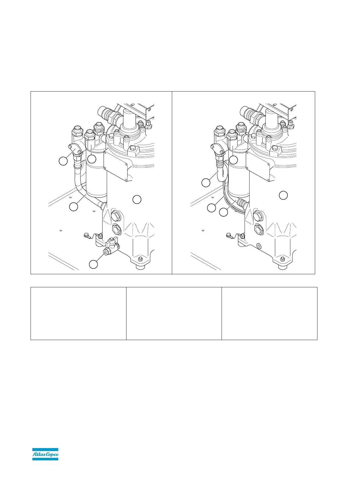
Figure 3: Modifications to vessel and oil filter pipe/housing to install the ER unit on 11
+
-30 kW and 15-30 kW (VSD)
Before modifications
After modifications
10. Oil pipe (from vessel to oil inlet oil
filter pipe / oil filter housing)
11. Oil drain
12. Oil separator vessel
13. Oil filter pipe with 2
nd
bypass valve
and oil filter housing
14. 2
nd
bypass valve (BV2) of filter pipe
15. Oil flexible (from vessel to oil inlet
connection of ER unit)
16. Oil flexible (from oil outlet
connection of ER unit to oil filter
pipe)
19. Wiring for oil temperature sensors
(2 off)
To enable the energy recovery unit to be inserted into the compressor oil circuit, the oil pipe (Figure 3-10) between the oil
separator vessel (Figure 3-12) and the oil filter housing (Figure 3-13) must be removed. This pipe will NOT be reused and
may be discarded.
 Loading...