20/06/2011 PM 9845 0512 02 Page 15 of 36
External modifications
To define connection kit, please refer to document 9845 0132 00 on GBP or contact your official Atlas Copco Service
Specialist.
Make sure to install insulation on all exposed hot surfaces of external flexibles and metal parts of the compressor and ER
kit, to avoid injury. The insulation can be optionally ordered, see Part list for correct order numbers.
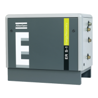
The oil inlet and outlet pipes of the ER unit are provided with a hose nipple to connect the oil hose assemblies.
Figure 6: ER Kit - overview Figure 7: Connection panel
A flexible (Figure 3/4/5-15) connects the outlet of the oil separator vessel (Figure 3/4/5-12) and the oil inlet connection
(Figure 7-5). The oil outlet connection (Figure 7-6) is connected to the bottom of the oil filter housing (Figure 3/4/5-13)
through a second flexible hose (Figure 3/4/5-16). This is the original connection of the oil pipe (Figure 3/4-10).
The ER unit should be placed as near as possible to the compressor. The water shut-off valves (2 off) are NOT supplied with
the kit.
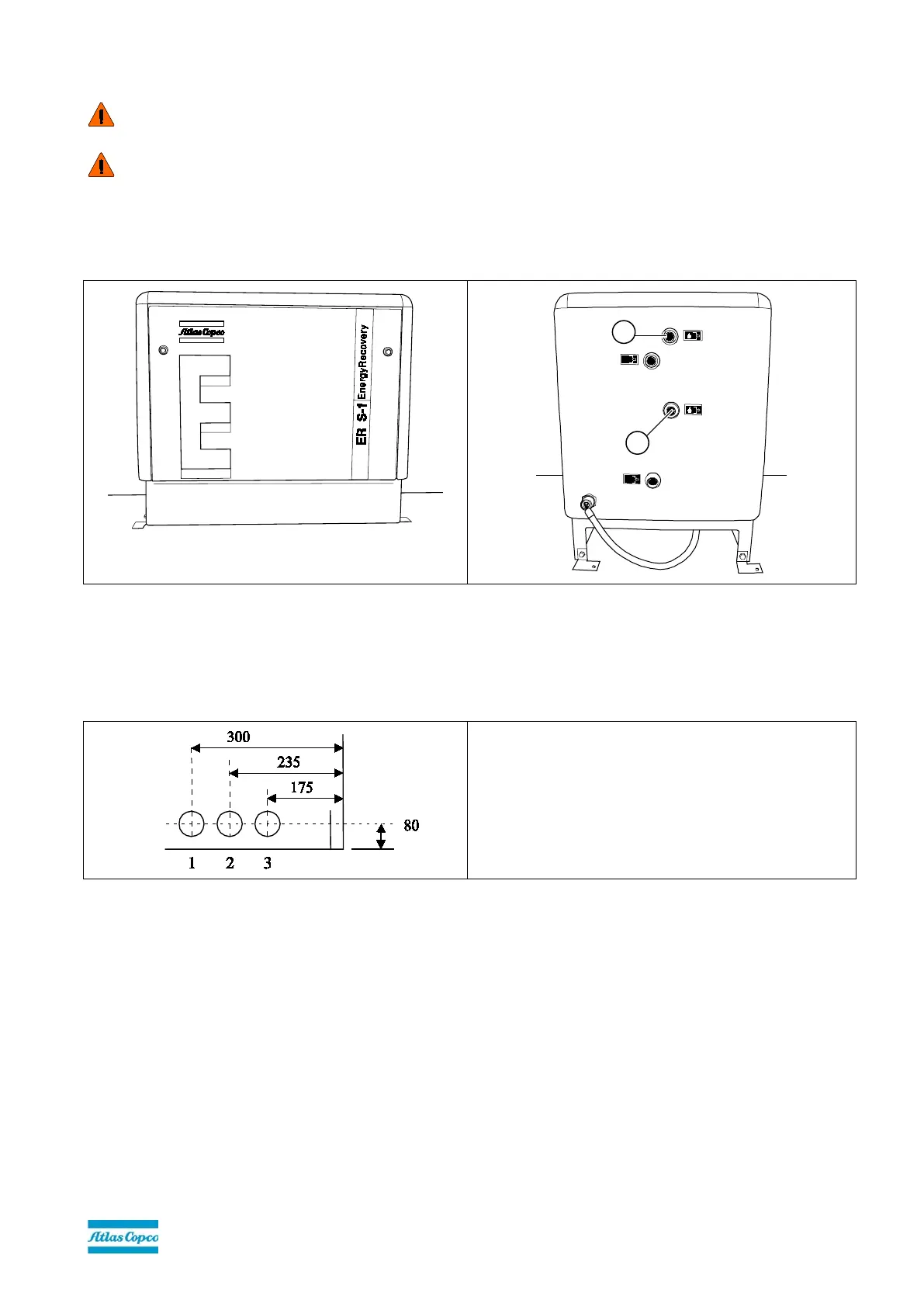
Figure 8: Example of a hole pattern to connect the ER kit and the compressor
1. Oil inlet ER
2. Oil outlet ER
3. Temperature sensor cables
To connect the ER unit to the compressor, make 3 holes in the side panel of the canopy (see Figure 8):
•
ø 55 mm (up to 90 kW)
•
ø 70 mm (from 90
+
kW on)
 Loading...