2920 1351 01
15
Instruction book
3 OPERATING INSTRUCTIONS
Safety precautions
The operator must apply all relevant safety precautions,
including those mentioned in this book.
Altitude operation
Consult Atlas Copco if operating above 3000 m.
Moving/lifting
The dryer can be moved by a lift truck using the slot in the
frame. Make sure that the forks protrude from the other side of
the frame. The dryer can also be lifted after inserting beams in
the slot. Make sure that the beams cannot slide and that they
protrude from the frame equally. The chains must be held
parallel to the bodywork by chain spreaders in order not to
damage the dryer. The lifting equipment must be placed in
such a way that the dryer will be lifted perpendicularly. Lift
smoothly and avoid twisting.
3.1 Initial start (Fig. 10)
1. At least 4 hours before starting, the mains supply to the
dryer must be switched on to energize the crankcase heater,
which warms up the oil. The indicator lamp (H1) is then
alight.
2. Open the refrigerant shut-off valves (11-Fig. 2 and on water-
cooled dryers also 4-Fig. 5a) as follows: take the protecting
cap off the valve, then screw the spindle fully out and refit
the cap.
3. On air-cooled dryers, press run/stand-by button (S1). Check
that the sense of rotation of the fan motor is correct. Cooling
air must be drawn in through the condenser (3-Figs. 4) and
blown over the refrigerant compressor (M1-Fig. 4a) to
outside the dryer. If wrong, switch off the voltage and reverse
two of the three phase connections at the mains terminals.
3.2 Starting (Fig. 10)
1. Switch on the voltage at least 4 hours before starting, to
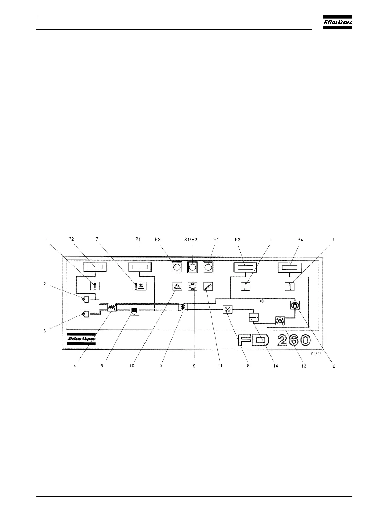
H1. Indicator lamp, voltage on
H2. Indicator lamp, dryer on
H3. Alarm indicator lamp, high pressure
dewpoint temperature
P1. Pressure dewpoint temperature gauge
P2. Temperature gauge, air inlet 1)
P3. Temperature gauge, evaporating
temperature 1)
P4. Temperature gauge, condensing
temperature 1)
S1. Run/stand-by button
The numbered items are
pictographs for:
1. Temperature
2. Air inlet
3. Air outlet
4. Air/air heat exchanger
5. Air/refrigerant heat exchanger
6. Condensate trap
7. Pressure dewpoint temperature
8. Refrigerant expansion valve
9. Start/Stop button
10. Alarm
11. Voltage on
12. Refrigerant compressor
13. Condenser
14. Refrigerant liquid dryer
1) Optional equipment
Fig. 10. Instrument panel
 Loading...