2920 1351 01
4
Instruction book
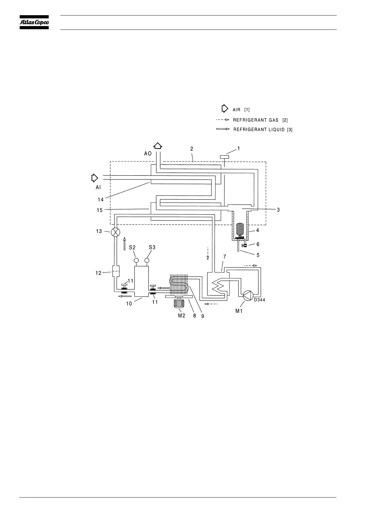
AI. Air inlet connection
AO. Air outlet connection
M1. Refrigerant compressor/motor
M2. Condenser cooling fan motor
S2. High pressure shut-down switch
S3. Fan control switch
1. Pressure dewpoint temperature
gauge
2. Insulating block
3. Cyclone condensate separator
4. Condensate trap with automatic
discharge
5. Automatic condensate drain hose
6. Manual condensate drain valve
7. Liquid separator
8. Fan
9. Refrigerant condenser
10. Liquid refrigerant receiver
11. Refrigerant shut-off valve
12. Liquid refrigerant dryer/filter
13. Refrigerant expansion valve
14. Air/air heat exchanger
15. Air/refrigerant heat exchanger/
evaporator
Fig. 2. Air and refrigerant flow diagram, air-cooled dryers
 Loading...