2920 1351 01
5
Instruction book
1.3 Refrigeration circuit (Fig. 2)
Compressor (M1) delivers hot, high-pressure refrigerant gas,
which flows, via the coil of liquid separator (7), through
condenser (9) where most of the refrigerant condenses. On
air-cooled condensers, a fan control switch (S3) stops and starts
the fan motor (M2) at falling or rising condenser pressure. On
water-cooled condensers, an automatic valve (3-Figs. 5)
regulates the cooling water flow, thus controlling the
temperature, which is directly dependent on the pressure. The
cooled refrigerant then collects in receiver (10).
The liquid leaves the receiver (10) via its syphon outlet and
flows through liquid refrigerant filter/dryer (12) to expansion
valve (13) where it expands to evaporating pressure.
In expansion valve (13) some of the expanding liquid refrigerant
evaporates, for which the required heat is withdrawn from the
refrigerant itself.
The refrigerant enters the heat exchanger/evaporator (15) where
it withdraws heat from the compressed air by further
evaporation. Dependent on the compressed air load, all, or
almost all, refrigerant evaporates at constant pressure and
temperature. The vapour refrigerant leaving evaporator (15)
flows into liquid separator (7). The liquid separator prevents
any droplets from entering compressor (M1) because warm
refrigerant, leaving the compressor, flows through the coil of
the liquid separator and evaporates the surrounding liquid.
From liquid separator (7) the refrigerant gas is sucked in by the
compressor.
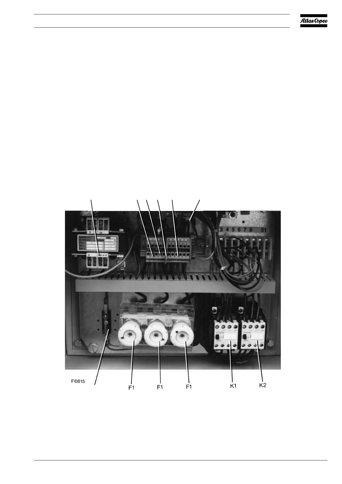
F1. Fuses, fan motor
F2. Fuse, secondary side (24 V) of transformer
K1. Motor contactor, refrigerant compressor
K2. Motor contactor, condenser cooling fan
L1/3. Terminal, mains
PE. Earth terminal
T1. Transformer
1X1. Terminal strip
Fig. 3. Electric cubicle of FD260
T1 L1 L2 L3 1X1 PE
F2
 Loading...