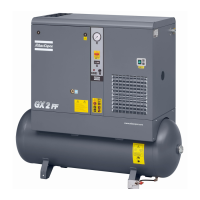
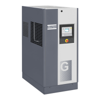
To modify the wiring for an operating voltage of 208 V or 460 V , both compressor main cubicle and
transformer dryer cubicle should be rewired as described below:
1. Required modifications in the compressor cubicle:
Step Action
1 Adjust the motor overload (FM1) setting.
2 Rewire the control transformer (T1)
3 Replace the control fuses (F1) with the 10,3 x 38mm 1 A or 2 A fuses provided (see further).
4 Modify the motor terminal bridge configuration in the main cubicle for the desired voltage.
5 Replace the voltage sticker by the appropriate voltage sticker provided.
6 On FF units, replace the power fuses (F10 in the main cubicle, F11 in the power
transformer cubicle) with the CC type 5 A, respectively 7,5 A fuses provided.
7 Modify the power transformer terminal bridge configuration in the transformer cubicle for
the desired voltage.
To adjust the motor overload (FM1) setting, simply rotate the adjustment screw (1) on the front of the overload
relay to the required setting (see table below).
Adjustment screw of the motor overload
Instruction book
34 2920 7054 00

 Loading...


