11
INPUTS AND RELAYS
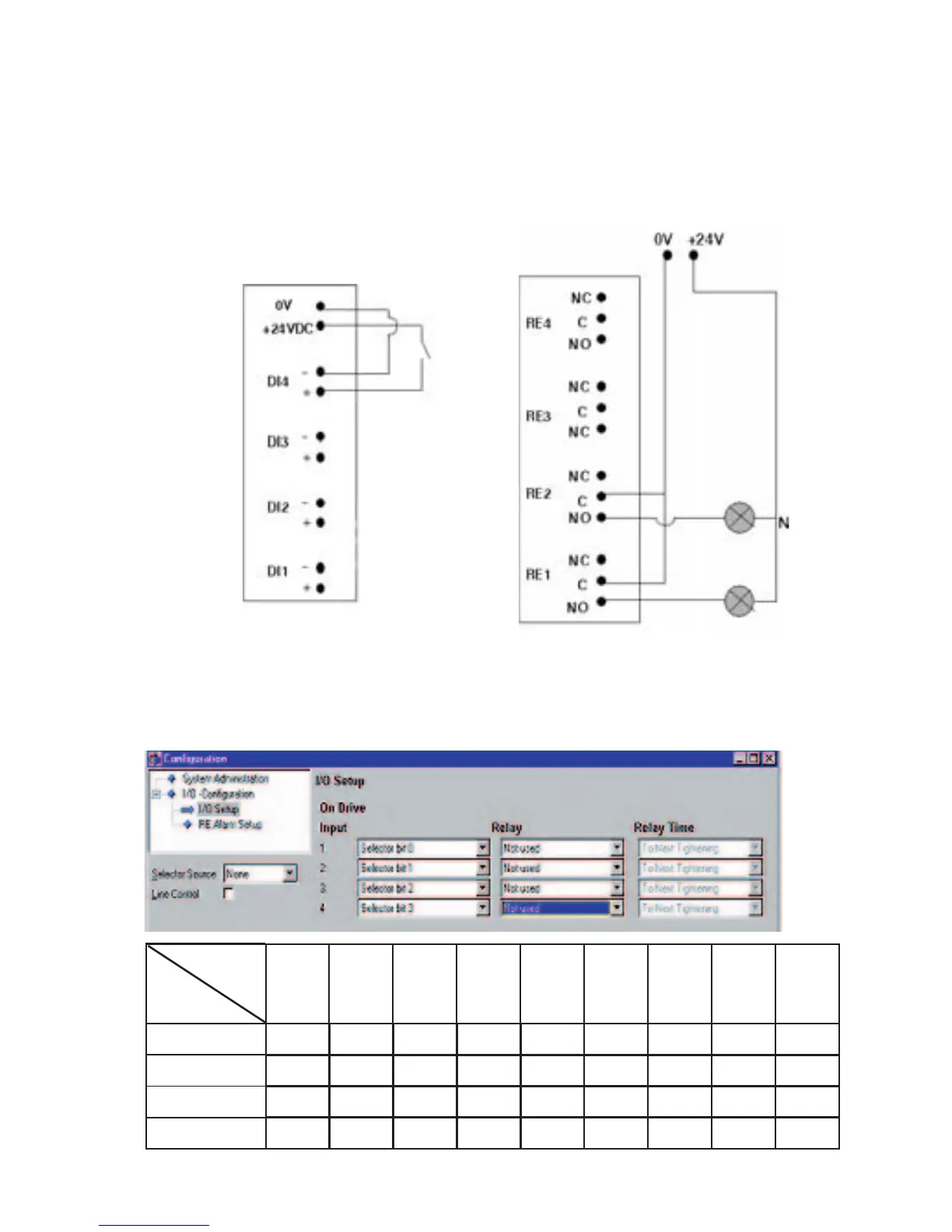
Figure 1 shows how to connect in order to obtain a signal on one of
the digital inputs. The power source can either be built in 24 VDC or
an external power source. Figure 2 shows how to connect to obtain
OK and NOK signals using relay outputs RE1 & RE2.
By programming the inputs with Selector bit 0-3, see figure 3, it
is possible to have up to eight different p-sets. The inputs are
interpreted binary according to the table below.
Figure 1 Figure 2
Figure 3
Parameter
set
Selector bit 012345678
0 010101010
1 001100110
2 000011110
3 000000001

 Loading...