Fast Track Guide 2. Installing the Mediant 1000
Version 5.0 11 October 2006
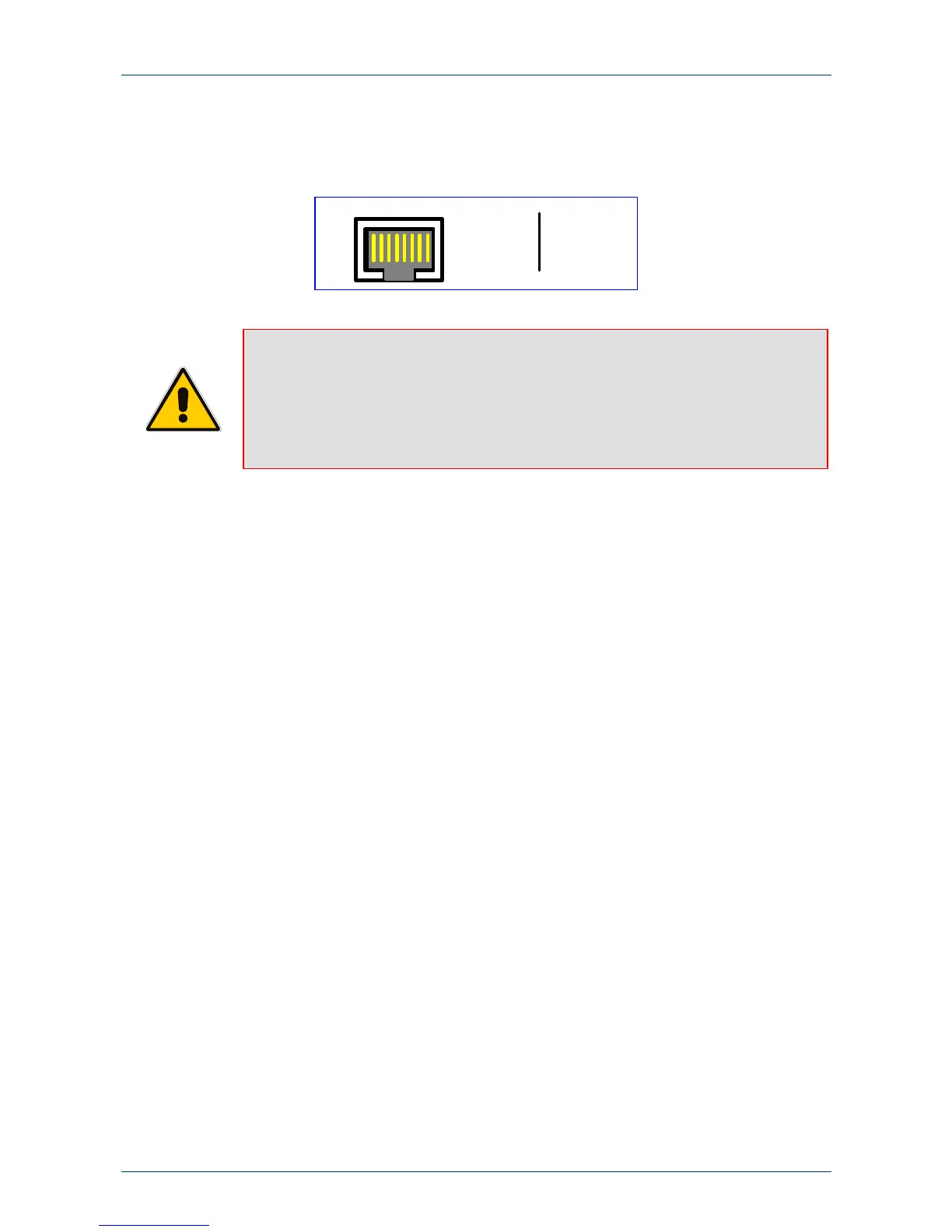
4. Connect the first Ethernet connection (labeled I), located on the CPU module of the Mediant
1000 front panel, directly to the network using a standard RJ-45 Ethernet cable (and the
second connection as optional redundancy / backup). For the connector pinouts, refer to
Figure 2-3 below.
Figure 2-3: RJ-45 Ethernet Connector Pinouts
1 2 3 4 5 6 7 8
4, 5, 7, 8
not
connected
1 - Tx+
2 - Tx-
3 - Rx+
6 - Rx-
Notes:
• For redundancy, it is recommended to connect each of the Ethernet
connectors to a different switch.
• When assigning an IP address to the Mediant 1000 using HTTP (in Step 1,
Section 3.1.1), you may be required to disconnect this cable and re-cable it
differently.
5. Using the supplied RS-232 cable, connect the Mediant 1000 RS-232 port (Labeled I0I0) to
either the COM1 or COM2 RS-232 communication port on your PC. Using the RS-232 port is
optional.
6. If you want to set up a dry contact system (future support), refer to the Mediant 1000 User's
Manual.
7. If you want to set up an audio system (future support), refer to the Mediant 1000 User's
Manual.
8. Connect the left (active) 100-240V~50-60 Hz power socket to the mains using the supplied
cord.

 Loading...


