J-33
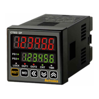
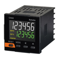
LCD Display Counter/Timer
(A)
Photoelectric
Sensors
(B)
Fiber
Optic
Sensors
(C)
Door/Area
Sensors
(D)
Proximity
Sensors
(E)
Pressure
Sensors
(F)
Rotary
Encoders
(G)
Connectors/
Connector Cables/
Sensor Distribution
Boxes/Sockets
(H)
Temperature
Controllers
(I)
SSRs / Power
Controllers
(J)
Counters
(K)
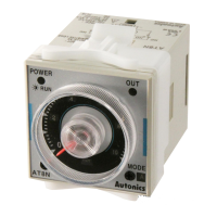
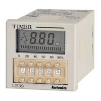
Timers
(L)
Panel
Meters
(M)
Tacho /
Speed / Pulse
Meters
(N)
Display
Units
(O)
Sensor
Controllers
(P)
Switching
Mode Power
Supplies
(Q)
Stepper Motors
& Drivers
& Controllers
(R)
Graphic/
Logic
Panels
(S)
Field
Network
Devices
(T)
Software
●
Follow instructions in ‘Cautions during Use’. Otherwise, it may cause unexpected accidents.
●
In case of 24-48VDC, 24VAC model, power supply should be insulated and limited voltage/current or Class 2, SELV power supply device.
●
Use the product, 0.1 sec after supplying power.
●
When supplying or turning off the power, use a switch or etc. to avoid chattering.
●
Install a power switch or circuit breaker in the easily accessible place for supplying or disconnecting the power.
●
Keep away from high voltage lines or power lines to prevent inductive noise.
In case installing power line and input signal line closely, use line lter or varistor at power line and shielded wire at input signal line.
Do not use near the equipment which generates strong magnetic force or high frequency noise.
●
This unit may be used in the following environments.
①
Indoors (in the environment condition rated in ‘Specications’)
②
Altitude max. 2,000m
③
Pollution degree 2
④
Installation category II
Cautions during Use
Factory Default
※
1: For 1-stage setting model (CX6 -1P
)
,
OUT1
does not appear.
The output time of
OUT2
is displayed as
OUtT
.
※
2: This is for the voltage input (PNP)/no-voltage input (NPN) selectable model (CX6 - ).
-
Parameter
Factory default
CX6 - CX6 - F
Counter
I
nM
UD-C UD-A
OUt
M
F F
CPS 30
-
OUT2
(
OUtT
※
1
)
HOLD
(xed)
HOLD
(xed)
OUT1
※
1
0)10 0)10
DP
------ ------
R
ESET
20
ms
-
SIG
NPN
-
SClDP
-.-----,
-.-----,
SCL !00000 !00000
TOTAL
※
2
OFF
-
START
000000 000000
DATA
CLR CLR
Timer
U-D
UP UP
OUt
M
OND OND
OUT2
(
OUtT
※
1
)
HOLD HOLD
OUT1
※
1
0)10 0)10
tRNG
99(999
s
99(999
s
SIG
※
2
NPN
-
IN
-T
20
ms
-
LOCK
lOFF lOFF
SET1
1000 1000
SET2
5000 5000
When SET1 is greater than SET2
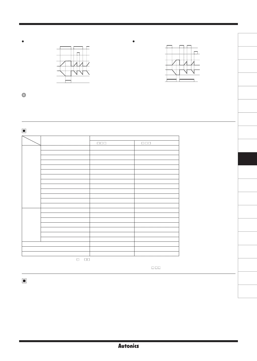
6) NFD.1 (ON-OFF Delay1) mode [
NFd1
]
Set ‘0’ for Off_Delay setting time. Set ‘0’ for On_Delay setting time.
In case of OND[
OND
], OND.1[
ONd1
], OND.2[
ONd2
] , or OND.3[
ONd3
] output mode,
●
UP mode: When timer setting value 1 (SET1) is greater than setting value 2 (SET2),
OUT1
output does not turn ON.
●
DOWN mode: When timer setting value 1 (SET1) is greater than setting value 2 (SET2),
OUT1
oututput does not turn ON.
When timer setting value 1 (SET1) and setting value 2 (SET2) are same,
OUT1
output turns ON when applied the start signal.
RESET
On_Delay
0
On_Delay
OUT2
(OUT)
INA (START)
0
Up
Display
Down
RESET
Off_Delay
0
Off_Delay
OUT2
(OUT)
INA (START)
0
Up
Display
Down
 Loading...