J-14
CX Series
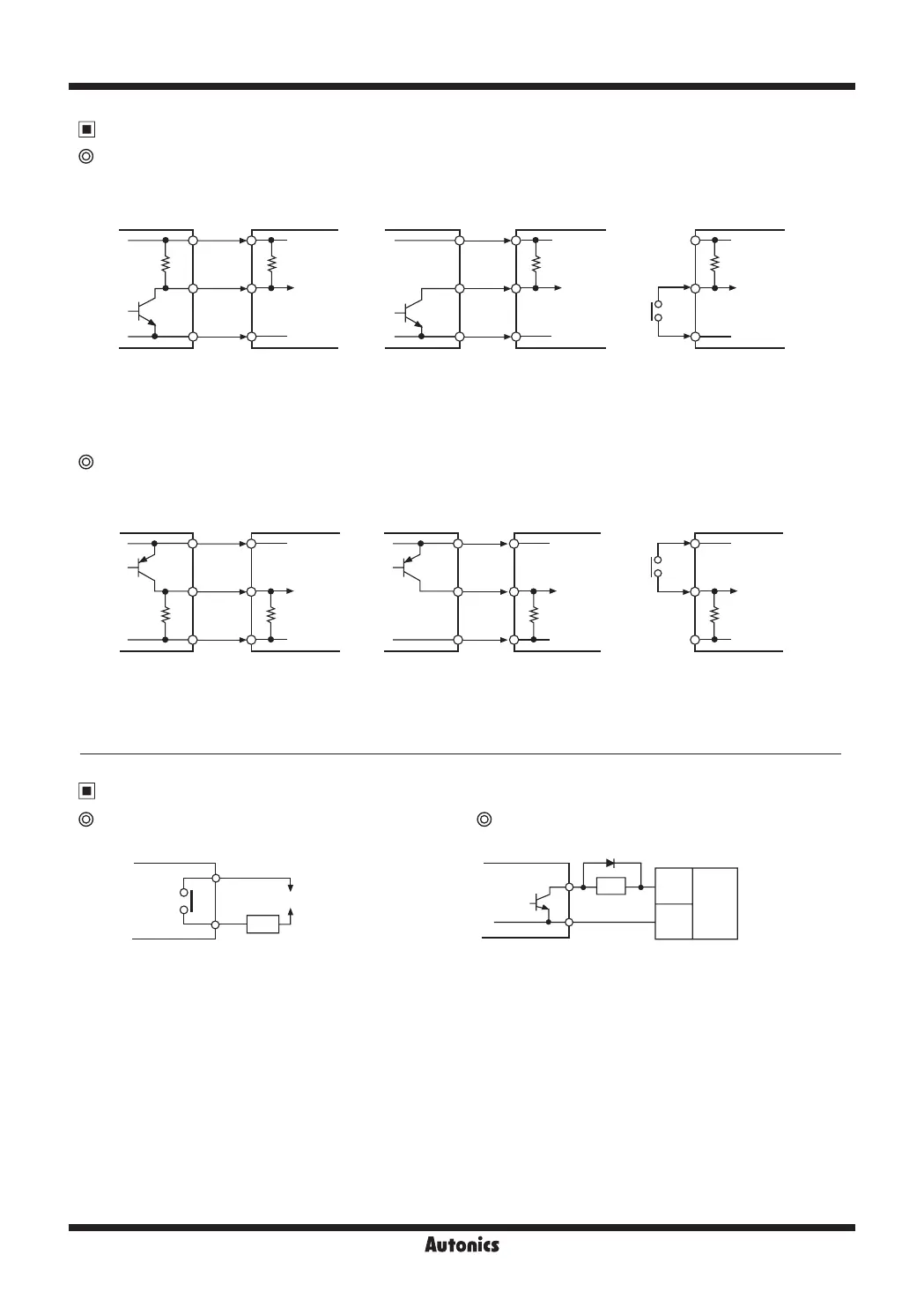
Input Connections
※
1:
CP1, CP2 (INHIBIT), SET input part
※
2: Set counting speed as 1 or 30cps.
No-voltage input (NPN)
● Solid-state input (standard sensor: NPN output type sensor) ● Contact input
5.4kΩ
5.4kΩ 5.4kΩ
+12V
+12V +12V
0V
0V 0V
Inner circuit
of input part
Inner circuit
of input part
Inner circuit
of input part
Sensor
(NPN output) (NPN open collector output)
Sensor
Brown Brown
Black Black
※
1
※
1
※
2
Blue Blue
Counter/Timer Counter/Timer Counter/Timer
Voltage input (PNP)
● Solid-state input (standard sensor: PNP output type sensor) ● Contact input
※
1:
CP1, CP2 (INHIBIT), SET input part
※
2: Set counting speed as 1 or 30cps.
10.8kΩ
10.8kΩ 10.8kΩ
+12V
+12V +12V
0V 0V 0V
Inner circuit
of input part
Inner circuit
of input part
Inner circuit
of input part
Sensor
(PNP output)
(PNP open collector output)
Sensor
Brown Brown
Black Black
※
1
※
1
※
2
Blue Blue
Counter/Timer
Counter/Timer Counter/Timer
Output Connections
Contact output Solid-state output
※
Select the load which capacity is not over contact
capacity.
※
For solid state output, select load power and load not to be over
(max. 30VDC, 100mA), swithching capacity.
※
Do not supply reverse polarity voltage.
※
1: For using inductive load (relay, etc.), connect surge absorber
(diode, varistor etc.) at the both ends of load.
※
1
Counter/Timer
Counter/Timer
Load
Load
(+)
(
-
)
Power
for load
(DC)
(Power of load)
 Loading...