EasyManua.ls Logo

Autronica AutroSafe BSD-340 User Manual

Autronica AutroSafe BSD-340
27 pages
To Next Page IconTo Next Page
To Previous Page IconTo Previous Page
Page #15 background imageLoading...
Page #15 background image
BSD-340-user-guide-eng, Doc. 1004474-2, 2020-09-18,
Autronica Fire and Security AS
Page 13
3.7 Raise loop and store topology in loop driver
a. Type #si and enter in the Command input window to raise loop and save topology to
EEPROM
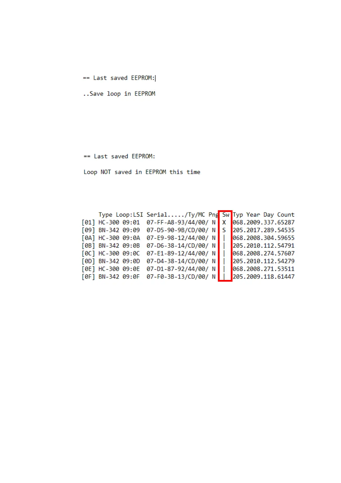
b. The loop raise should end with a message like this
If loop is successfully saved to EEPROM, proceed to step d.
c. Resolving failed save of topology
i. If there are devices on the loop which fail to start, or that there are loop breaks on the
loop, a fail message is reported: Loop Not saved in EEPROM this timewill be printed
in terminal (see figure below)
ii. Since the powerloop requires to have a saved topology to work, use the print
topology #prntop command to get a printout of the topology and fault messages to
help resolve any faults.
iii. Note the symbol | in the Sw column. Different symbols may be used:
| = closed switch, X = open switch, ? = unit missing, S = Short circuit
In the example above there is a short between detector 1 and 2. In the SW column
the first detector states an X, which means that it has not been able to close the loop
switch. On detector 2 it is stated an S for short (towards detector 1)
iv. Investigate the loop and connections and resolve any faulty wiring or connections.
v. Type #si and enter in the Command Input Window to try a loop raise again after you
have investigated faults indicated on the topology after the last run of "si.
d. After loop has been successfully saved you can verify the saved loop, Type #prntop and
enter in the Command input window to list saved topology (output as in figure below)

Table of Contents

Question and Answer IconNeed help?

Do you have a question about the Autronica AutroSafe BSD-340 and is the answer not in the manual?

Autronica AutroSafe BSD-340 Specifications

General IconGeneral
BrandAutronica
ModelAutroSafe BSD-340
CategoryMeasuring Instruments
LanguageEnglish

Summary

1. Preface

1.1 PRODUCT WARNINGS

Important safety warnings for product installation and operation.

1.2 WARRANTY DISCLAIMERS

Legal disclaimers regarding product warranties and representations.

1.3 Target audience

1.4 Changes

1.4.1 Stored loop topology

Explains saving loop topology to EEPROM for control and identification.

1.4.2 New fault message: "Memory fault"

Details a new fault message related to topology saving or EEPROM corruption.

1.4.3 Other changes

Lists other software improvements in version 1.1.0, affecting loop handling.

1.5 Safety

1.6 Compatibility

1.6.1 AutroSafe IFG

Specifies software version compatibility between BSD-340 and AutroSafe IFG.

1.6.2 Loop units

Lists compatible loop unit software versions for BSD-340.

1.7 Tools

2. PowerLoop – how it works

2.1 Powerloops versus normal detector loops

Compares PowerLoop functionality with standard detector loops.

2.2 PowerLoop

Details the PowerLoop system, its electrical properties, and software handling.

2.2.1 Electric properties

Details the electrical specifications of the PowerLoop system.

2.2.2 Software handling

Explains the "raising" process for a PowerLoop and special cases.

2.2.3 Loop wiring

Discusses the importance of loop wiring and cable length for PowerLoops.

2.3 Loop handling

Describes loop handling procedures including topology reporting and reset.

2.3.1 Reporting topology to AutroSafe

Describes how the BSD-340 reports loop topology during AutroSafe INIT.

2.3.2 Loop handling / RESET

Explains the process of loop handling and reset for fault resolution.

2.3.3 Loop Polling

Details how AutroSafe polls detectors to ensure they are active.

2.4 Crosstalk

Defines crosstalk and its impact on PowerLoop communication.

2.4.1 Possible crosstalk issues

Lists potential problems arising from crosstalk events.

2.4.2 Crosstalk countermeasures

Outlines methods to mitigate crosstalk issues in PowerLoop systems.

2.5 Duplicate messages

Explains how duplicate messages are handled and their potential impact.

3. Upgrading BSD-340 PowerLoop Drivers

3.1 Before you start

Pre-upgrade steps, including downloading files and checking system numbers.

3.2 Label the BSD-340 board to identify the SW version

Instruction on labeling the board with the target SW version for upgrade.

3.3 Connect PC to loop driver

Guide for physically connecting a PC to the BSD-340 service port.

3.4 Start IFG Service tool and connect to loop driver

Steps to launch and establish a connection using the IFG Service Tool.

3.5 Disable loop

Instruction to disable the loop on the Autrosafe panel before upgrade.

3.6 Download software to BSD-340

Detailed steps for downloading EEProm and Application files to the BSD-340.

3.7 Raise loop and store topology in loop driver

Procedures for raising the loop and saving its topology to EEPROM.

4. Service operations

4.1 Delete and save topology

Procedures for deleting and saving loop topology.

4.1.1 Delete topology

Methods for deleting existing loop topology from the driver.

4.1.2 Save topology

Procedures for saving a new loop topology.

4.2 Replace PowerLoop driver (BSD-340)

Procedures for replacing the BSD-340 PowerLoop driver.

4.2.1 Without PC and IFG service tool

Steps to replace the BSD-340 driver without using PC software.

4.2.2 With PC and IFG service tool

Steps to replace the BSD-340 driver using the IFG Service Tool.

4.3 Replace loop unit

Procedures for replacing a loop unit.

4.3.1 Without PC and IFG service tool

Instructions for replacing a loop unit without PC software.

4.3.2 With PC and IFG service tool

Instructions for replacing a loop unit using the IFG Service Tool.

5. Commissioning operations

5.1 Useful commands

Lists and describes essential commands for commissioning.

5.2 Establish AutroFieldBus communication

Procedure to establish communication on the AutroFieldBus.

5.3 De-conflict systems

Procedures for de-conflicting systems and PowerLoops.

5.3.1 Changing system number

How to change system numbers to avoid conflicts between PowerLoops.

5.4 Crosstalk

Details on crosstalk detection, management, and analysis.

5.4.1 +40 setting

Explains the purpose of the +40 setting for crosstalk management.

5.4.2 Discover crosstalk

Method to detect and identify crosstalk issues.

5.4.3 Crosstalk map

Visual representation of crosstalk detected between loops.

5.4.4 List crosstalk statistics

Command to display statistics for crosstalk on a specific loop driver.

5.4.5 PowerLoop statistics (#PL_Stat)

Command to display internal statistics of the PowerLoop driver.

5.5 Serial numbers for verification (Recommended)

Using serial numbers and topology listing for verification.

6. External protocols

7. IFG service tool- user interface

8. Troubleshooting

8.1 Open loop and short circuit on the same loop may end up in infinite disable/enable

Troubleshooting steps for simultaneous open loop and short circuit issues.

8.2 Parameter fault on loop unit

How to resolve parameter faults on loop units.

8.3 Enable loop without saved topology

Warning against enabling loops without saved topology due to potential issues.

8.4 Memory fault after initialization

Causes and resolution for memory faults after initialization.

8.5 Open loop after initialization

Troubleshooting open loop issues that occur after initialization.

Related product manuals