Reference Section • 89
Chapter 5
Headstage
• Principles and properties of the V-Clamp and I-Clamp circuits in the CV-7A
headstage.
• See also Feedback Resistor, Mode, Noise, Series Resistance Compensation.
The CV-7A headstage contains two distinct circuits, a current-to-voltage (I-V)
converter used in V-Clamp mode, and a voltage follower used in I-Clamp mode. The
I-V converter is similar to that found in an Axopatch-1D headstage, whereas the
voltage follower is like that in an Axoclamp 2B headstage.
Voltage Clamp Circuit
In V-Clamp mode, the goal is to hold the interior of an electrode at a command
potential while measuring the currents that flow down the electrode. An I-V converter
achieves this by producing a voltage output that is proportional to the current input.
There are two types of I-V converters used in patch clamp headstages: capacitive
feedback (used in the Axopatch 200B), and resistive feedback (used in the
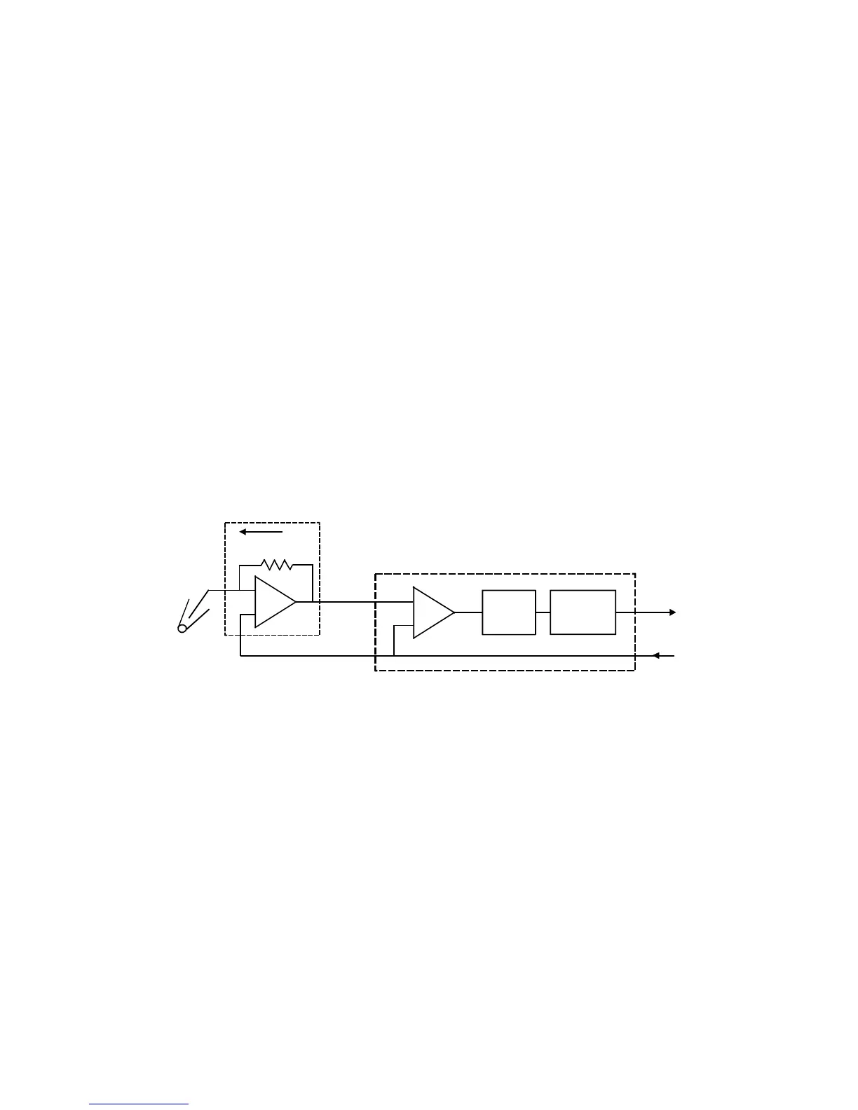
Axopatch-1D and in the MultiClamp 700A). The essential parts of a resistive-feedback
headstage are shown in Figure 4.11.
+
V
p
BOOST
-
+
-
R
I
f
OFFSET
AND
SCALING
HIGH-
FREQUENCY
BOOST
I
V
o
CIRCUIT
f
PROBE
Figure 4.11. Resistive-feedback headstage.
The heart of the circuit is an operational amplifier (op amp) in the PROBE. The
behavior of this circuit depends upon two characteristics of an ideal op amp.
 Loading...