Tutorials • 17
Chapter 3
Tutorial 2 – Electrode in the Bath: Current Clamp
Note that the model cell used in this tutorial is designed to simulate a patch pipette,
rather than a typical intracellular electrode, which generally has a higher resistance.
However, the principles illustrated are the same.
1. Set up the MultiClamp 700A and the MultiClamp Commander as in Steps 1-3 of
Tutorial 1.
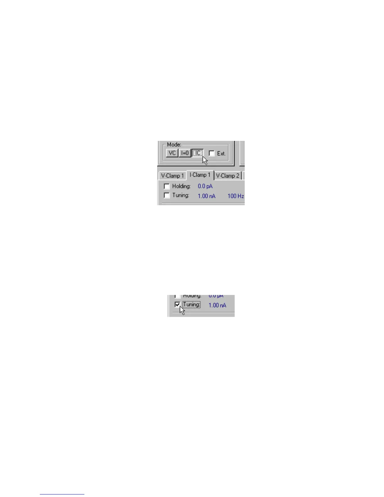
2. Under Channel 1 Mode: press the button labeled IC. The tab labeled I-Clamp 1
will select, and the Current Clamp light on the front panel of the MultiClamp 700A
unit will illuminate.
Figure 2.8
Note that the Scaled Output signal displayed on the oscilloscope is now Membrane
Potential (1 V/V), as shown in the Output Signals section of the MultiClamp
Commander.
3. Press the Pipette Offset button. This operates exactly like in Voltage Clamp mode.
(See Tutorial 1, Step 4.) Note how the Scaled Output signal changes on the
oscilloscope.
4. Check the Tuning checkbox.
Figure 2.9
 Loading...