16 • Tutorials
MultiClamp 700A Theory and Operation, Copyright 2000, 2001 Axon Instruments, Inc.
A repetitive pulse appears on the Membrane Current output. (The trace can be
triggered on the oscilloscope screen by making a connection from the SYNC
output on the rear of the MultiClamp 700A to the External Trigger input on the
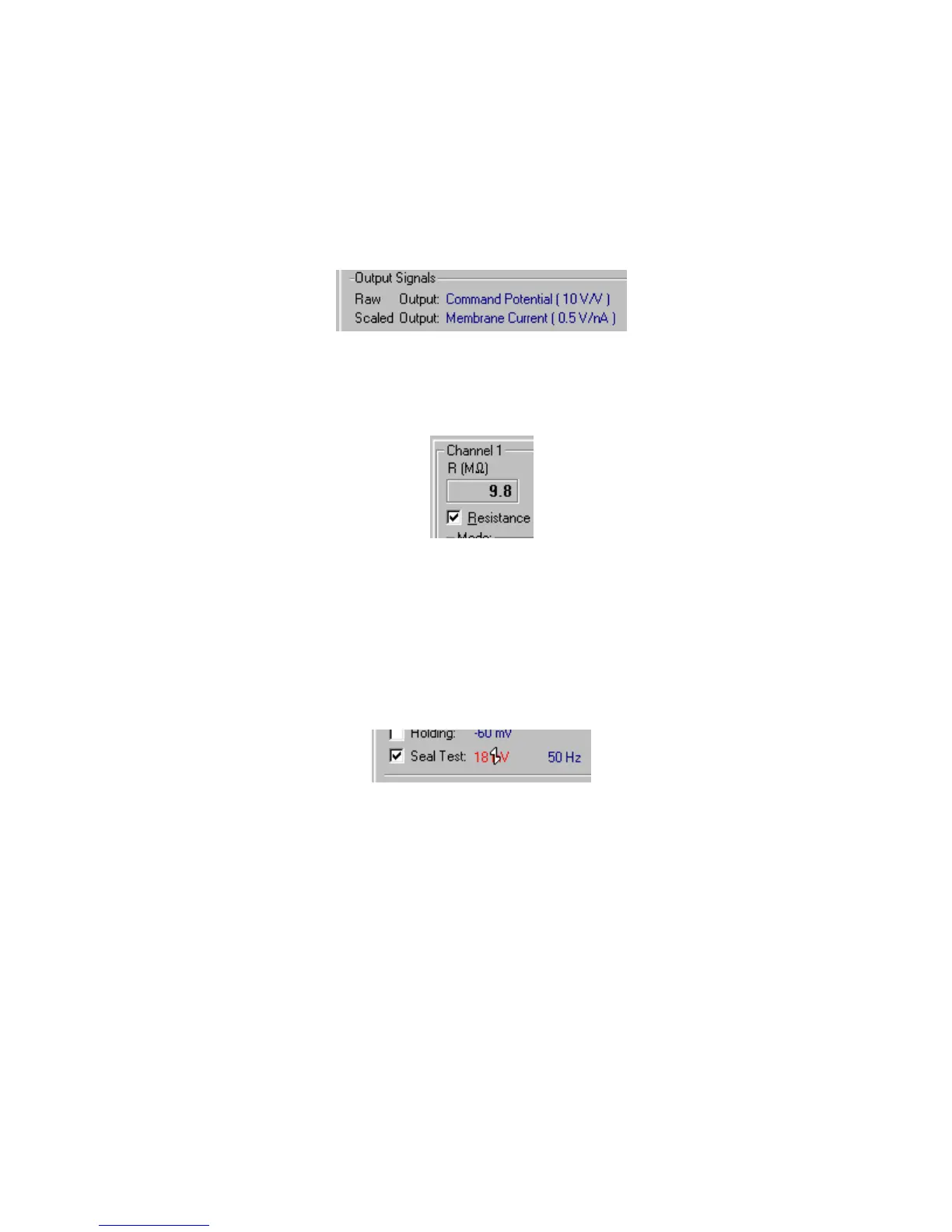
oscilloscope.) The amplitude of the Seal Test pulse is 10 mV. The amplitude of
the Membrane Current output pulse is 0.5 V, which corresponds to 1 nA at the
default gain of 0.5 V/nA (shown under Scaled Output in the Output Signals
section).
Figure 2.5
Therefore, the resistance of the model electrode is calculated from Ohm’s Law to
be R = V/I = 10 mV/1 nA = 10 MΩ. Alternatively, check the Resistance checkbox
under the Channel 1 meters.
Figure 2.6
The resistance is displayed on the meter. Uncheck the box when done. (DC
fluctuations in the signal are due to pulses from the MultiClamp Commander for
calculating meter resistance values.)
6. Try changing the Seal Test amplitude and frequency by using the glider control
with the mouse. (See
SETTING PARAMETERS IN THE MULTICLAMP
COMMANDER
in Chapter 2.)
Figure 2.7
Note how the Scaled Output signal changes on the oscilloscope as the test pulse
parameters are changed.
 Loading...