Tutorials • 23
Chapter 3
Tutorial 4 – Whole-Cell Configuration: Voltage Clamp
1. Reset to Program Defaults and set Seal Test frequency to 200 Hz. Plug the CELL
connector on the model cell into the headstage of the MultiClamp 700A.
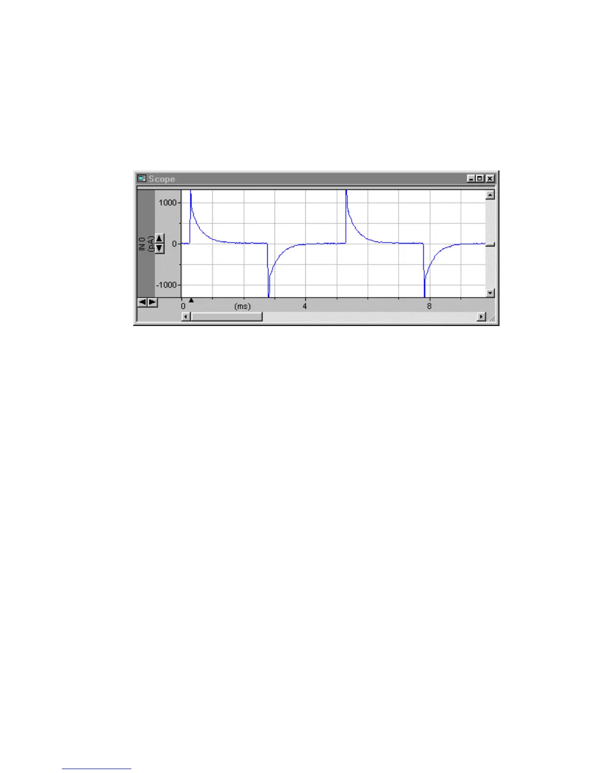
2. Check the Seal Test checkbox; a train of ~0.5 Volt transients decaying over ~1 ms
will appear on the Scaled Output trace. (These are more easily seen if the
oscilloscope is triggered using the SYNC output of the MultiClamp 700A.)
Figure 2.16
The fast component of the transients reflects the simulated electrode capacitance
(5 pF), while the slow component reflects the capacitance of the simulated cell
(33 pF). Following the 10 mV Seal Test step the transients decay to a plateau of
10 mV, equivalent to a current of 20 pA. This yields a resistance of 10 mV/20 pA
= 500 MΩ, which is the “input resistance” of the model cell. This can also be
found by checking the Resistance checkbox under the meters.
 Loading...