24 • Tutorials
MultiClamp 700A Theory and Operation, Copyright 2000, 2001 Axon Instruments, Inc.
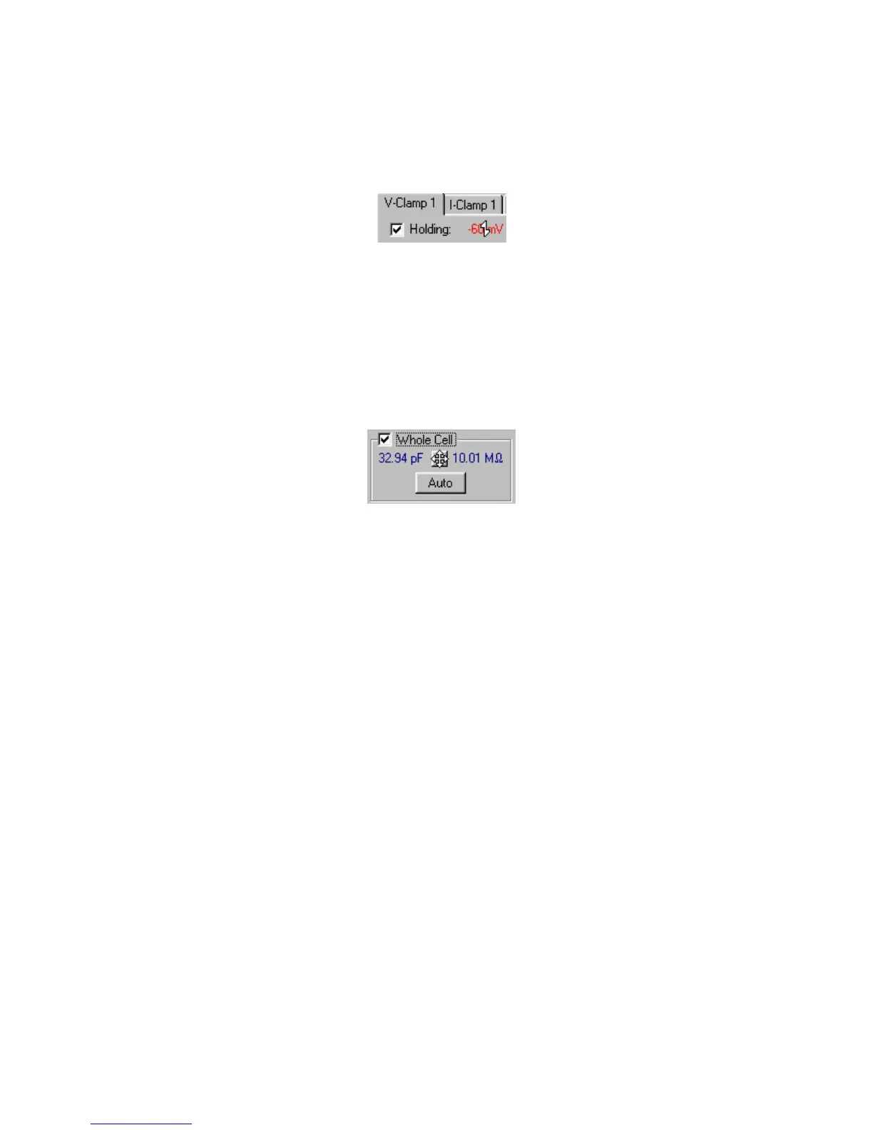
3. In a real cell, the holding potential would have been set prior to going to whole-
cell mode. (See Chapter 4.) Set the holding potential now by checking the
Holding checkbox and using glider control to apply a negative holding potential
(e.g. –60 mV).
Figure 2.17
4. We now wish to cancel the slow component of the transient, because (a) it may,
like the fast transient, saturate the headstage amplifier (see Tutorial 3), and (b) this
cancellation is necessary for series resistance compensation (see step 8, this
Tutorial). Check the Whole Cell checkbox and use the toggle button to adjust the
capacitance (pF) and series resistance (MΩ) parameters. (See Figure 2.18 below.)
It will be easier to do this while holding down the Shift key to magnify the effect
of mouse movement.
Figure 2.18
It should be possible to compensate completely the slow transient. The optimal
values will be around 30 pF (the model cell capacitance) and 10 MΩ (the model
electrode resistance). Note that a small, fast transient may reappear after the slow
one is canceled. This can be removed by again pressing the Cp Fast Auto button.
5. An alternative way to cancel the slow transient is by pressing the Auto button. Try
this, after first using glider control to set the pF and MΩ values to “wrong” values.
After imposing a series of voltage steps on the model cell, the algorithm should
converge on about 30 pF and 10 MΩ. In real experiments it may be necessary to
make manual adjustments for optimum cancellation of the slow transient.
 Loading...